Showing posts with label anchorage of bars. Show all posts

Monday, January 25, 2016

Chapter 15.13 - Curtailment of Bent-up bars

In the previous section we saw the anchorage requirements of bent-up bars at simply supported ends and at end supports in frames. In this section we will see the case (iv) and (v) of fig.15.59.

Case (iv): Intermediate supports in continuous beams and slabs

The following fig.15.73 shows such a support.

Fig.15.73
Bent up bar at continuous support
Bent up bars can be used to resist hogging moments at intermediate supports in continuous systems. They must be given proper anchorage on both sides.

In the fig.15.67, the bar provided as bottom bar in span BC is bent-up at Q. It then becomes top steel at support C and continues as top steel into the span CD. Now, when the span BC bends downwards due to the applied loads, the bar will experience tension. So it will try to pull out from support C. To prevent this, we know that adequate development length should be provided, and from the discussion that we had about the 'development length of bent-up bars', we can say that the length RST should be greater than or equal to Ld. This will prevent the bar in span BC from pulling out from the support C.

This same bar will experience another tension also: At the support, the beam is bending upwards, so the bar is being pulled from span BC as well as from span CD. So the bar will try to pull into the support C from both sides. That is., from span BC and from span CD.

We will first consider span BC. The portion inside BC has a bent shape. So a bar with a bent shape is preventing the 'pulling into support C'. This situation requires a different method of measurement for Ld. It is shown in the fig. below:

Fig.15.74
Method of measuring Ld when the bent up bar is under hogging moment

From the fig.15.74, we can see that the procedure is simpler. We do not need to mark the point R. The measurement is taken from the bottom bend point Q towards the left side. The available length towards the left of Q should be greater than or equal to Ld. If this is satisfied, the bar will not 'contract' into support C from the span BC.

In a similar way, the bar will try to 'contract' into the support C from span DC also. To prevent this we must provide Ld from the face of the support towards the right side.

Now we will discuss about the performance of the bent-up bar in resisting the hogging moment at the support C. We have seen figs.15.51 and 52 which give the requirements of top bars at an intermediate support in a continuous beam. Fig.15.51 is shown here again for easy comparison.

Fig.15.51
Curtailment of 'straight' top bars


We can see that a bar is curtailed at a distance of La from the theoretical cut-off point. The other bars continue beyond the point of inflection, (two of them will continue even beyond the next support to act as stirrup hangers and also to take part in resisting the hogging moment at the next support. In a general simple case, there will be three bars at the top, and the middle one will be curtailed. If the hogging moment is of a larger magnitude, more than three bars will have to be provided in layers). Here we concentrate our attention on the bar which is cut-off at a distance La from the theoretical cut-off point. This actual cut-off point is close to the support. We can think of using a bent-up bar in the place of this bar. This is shown in the fig.15.75 below:

Fig.15.75
Bent up bar in place of curtailed bar at top of continuous support


From the fig., we can see that the horizontal portion ST can be extended to the desired point in the right side of support C. But it is not possible to do so in the left side, and thus it may not have the required length in the left side. So the bar will perform well on the right side of the support C. And any contribution that it makes to resist the hogging moment on the left side of C should be ignored. But this arrangement will create a sort of asymmetry because, on the right of support C, three bars (two stirrup hangers and one bent-up bar) are available, while on the left side, only the two stirrup hangers are available to take up the hogging moment. This is solved by bringing in the bent-up bar of span CD as top bar into span BC as shown in the fig. below:

Fig.15.76
Bent up bar at a support from adjacent spans

In the above fig., the two bars are shown at different levels only for clarity. In the actual beam, they are provided at the same level as indicated by the ‘0 mm’ clearance between the bars.

Now we will see the curtailment requirements when bent-up bars are provided. Earlier we have seen fig.15.51 (shown again above) which showed the curtailment details when straight bars are used. This fig. is based on the cl.26.2.3.4 of the code. The same requirements apply here also. So we can draw a fig. for bent-up bars by making suitable modifications to fig.15.47. This is given in fig.15.77 below:

Fig.15.77
Curtailment of top bars at an intermediate support when bent up bars are used
When bent up bars are used to resist hogging or negative moments at supports, they must be given required areas.

We can see that the bent-up bar from span CD is not included in the calculation of Ast1. This is because, it's top horizontal portion does not have the required length inside span CD. So it's contribution cannot be taken into account in span CD. But it's contribution can be taken into account in the span BC.

So we have completed case (iv) of fig.15.59. The next case (v) is similar to case (iv). To show a final diagram showing the curtailment details, all we need to do is to change the support condition in the above fig.15.77. This is shown below:

Fig.15.78
Bent up bars at the intermediate supports of a frame


So we have seen the final case (v) also of fig.15.59. It may be noted that for the cases (iii), (iv) and(v), Moment envelope should be used instead of Bending moment diagram where ever applicable.

Shape of Bent-up bars


We have seen the usage of bent-up bars in various situations. Now we will see an important aspect that we have to consider in the 'actual making' of a bent-up bar. In the figs. that we saw above, the bends are all shown as ‘sharp’, as in the fig. below:

Fig.15.79
Sharp bends shown in illustrations

But this is used only for illustration purpose. In an actual beam, such sharp bends should be avoided. This can be achieved by introducing curved portions in between straight segments as shown in the fig. below:

Fig.15.80
Actual method for forming a bent-up bar

Each of the curved portions at the top and bottom bend points is a part of a perfect ring having inner radius r and outer radius r + Φ. More details about the formation of such bent bars are given in IS 2502-1963: Code of practice for bending and fixing of bars for concrete reinforcement.

So we have completed the discussion about bent-up bars. In the next section, we will see the method of curtailment when the continuous members are designed using moment coefficients.

PREVIOUS       CONTENTS       NEXT                                          


Copyright©2016 limitstatelessons.blogspot.com - All Rights Reserved

Chapter 15.12 - Anchorage for Bent-up bars at supports

In the previous section we saw the compilation of the various requirements for the curtailment of Top and Bottom bars. In all those cases, we have used 'straight bars'. In this section we will see the use of 'bent-up' bars.

We have seen that some of the tensile bars can be curtailed at sections beyond which they are no longer required (after giving the required extensions). Instead of curtailing them at those sections, they can be bend upwards. The angle of bend is usually 45 to 60 degrees. After bending, these bars continue upwards up to the top face of the beam. (the required concrete cover should be provided at the top face). At the top face, these bars are given a bend once again so that they become horizontal again. After becoming horizontal, they continue towards the support.

The bending up of the bars is done near the supports. So we will discuss it at the same five cases that we saw earlier in fig.15.59 in the previous section.

In the first three cases, the bent up bars will not have space for required extension. So they must be given a standard 90o bend, so as to obtain the required Ld. In the last two cases, required space will be available for extension. So when they are extended, they will have enough length to contribute towards 'serving as a part of the negative top steel' required at the support. We will discuss each of the cases in detail.

Case (i) Simply supported ends: We know that a bar should be extended beyond the theoretical cut-off point by distance greater than or equal to La. We discussed this based on fig.15.25 to 27. Based on that, we must begin the sloping portion of the bar only at a distance of La from the theoretical cut-off point. But, when we provide a bent-up bar, it will intercept the diagonal crack. as shown in the fig.15.62 below:

Fig.15.62
Bent-up bar intercepting the crack
Bent-up bars intercept the cracks effectively, and prevents their development.

Because of this type of interception, the bent-up bars contribute towards reducing the spread of diagonal cracks. [This type of a contribution is not obtained from straight bars]. So we need not extend the bar to a distance of full La before beginning the sloping portion. According to cl.8.3 (b) of SP 34, for extension purpose, the bent-up bar may be considered to be effective up to the point where the bar crosses half of the effective depth of the beam. 

This can be explained as follows:
The bent-up bar originally travels through the bottom side of the beam. This is at the midspan region.  Near the support region, it is bent upwards. Once it is bent, the bar is no longer available at the bottom side. So we are tempted to think in this way:
• a bottom straight bar no longer contributes any thing at the bottom side after the cut-off point. 
• in the same way, the bent-up bar no longer contributes any thing at the bottom side, after the point of bent-up. 

Based on this, we will want to bring the point of bend up to the beginning of the crack as shown in the fig.15.63(b) below:

Fig.15.63
Extension for bent-up bar

Fig.(a) shows the original point r of the bent-up. But as we are required to provide an extension of La, the point of bent up is given at q as shown in the fig.(b). But this is not required. The tension in the bent-up bar is effective to resist the 'external applied moment Mu,x' shown in fig.15.26, even after the point of bent-up. Now the question arises: For how much 'more distance' is it effective? The answer is given by the above mentioned cl.8.3(b) of SP 34. 

Imagine a horizontal plane through half the effective depth of the beam. Any bent-up bar in that beam will have a point of intersection with the plane. This point of intersection will be in the 'sloping portion'. According to the clause, the tension in the bar at this point of intersection is effective in resisting Mu,x.  Based on this information, we can calculate the required extension. The calculations are based on fig.15.64 below:

Fig.15.64
Calculation of extension

The point of intersection between the bent-up bar and the horizontal plane through d/2 is our 'point of interest'. We want that point to be at the beginning of the crack. The above fig. shows exactly that. q' is the point of intersection, and it is on section YY which passes through the beginning of the crack. To this finalised position, we can add two triangles stq and str. With the help of those triangles, we calculate the required extension.

• sr is original position of the bent-up bar.
• tanα = st⁄tr = (d/2)⁄tr  . So tr = d/2 cotα.
• Similarly tanθ = st⁄qt = (d/2)⁄qt  . So qt = d/2 cotθ.

If we assume that the diagonal crack occurs at an angle θ = 45o and the bent up is also done at an angle of α = 45o, then we will get tr = qt = d/2.  (∵ tan45 = cot45 = 1). So, if we extend the horizontal portion of the bar beyond the section XX by a distance d⁄2 , and thus start the sloping portion from the point t, the point s will move horizontally to q’. So we can conclude that the additional extension that has to be given beyond the theoretical point of bent-up is La = tr = d ⁄2.

Now we will discuss about the development length requirements of bent-up bars. The fig.15.65 below shows a bent-up bar PQRSTU , provided in a beam.

Fig.15.65
Development length for bent up bar

The bend is given at Q. So the sloping portion begins at Q , and the angle of the bend is shown as α . [Bend can be given at Q only if the bar is no longer required to take up any sagging moment, and La =d/2 is given]. But from the discussion that we had based on fig.15.50, development length Ld should be provided on both sides of Q. As the portion on the left side of Q is having a sloping shape, we need a standard method to measure Ld on a sloping portion. 

This method is shown in the above fig.15.65 and can be explained as follows: The point R is marked on the bar. It is the point of intersection of the bar with a horizontal plane through d/2. The length available from R to the end of the bar is measured. This length should be greater than or equal to Ld . If at an end support, enough space is not available, then a standard 90o bend can be given at T. 

If the point Q is a little more away from the support, it may be possible to avoid the 90o bend. This is shown in the fig.15.66 below:

Fig.15.66
Development length of bent up bar with out standard 90o bend at the end

For the bar B in the above fig., the point Q at which the sloping portion begins, is further away from the support. So there is enough space to extend the bar, and a 90o bend can be avoided at the end.

As we are discussing about the bent-up bars at this stage, it will be better if we look at the performance of these bars as 'top bars' also. The above figs.15.65 and 15.66 can be used for this purpose. Earlier, we saw the method of providing top bars at a simple support of a beam using 'straight bars'. We discussed it based on fig.15.58 in the previous section. There we saw the quantity of bars to be provided. Now, in our present case, looking at the above fig.15.65, we can say that the portion STU can take part in resisting the hogging moment at the support. But we must consider the length of the horizontal portion ST. This length depends on the position of Q, and angle α. So it may not be always possible to get a sufficient length for ST to resist the hogging moment. Because of this, it is better to ignore any contribution made by the bent-up bar towards resisting the hogging moment at a simple support of a beam. Instead, we must use the two stirrup hanger bars to satisfy this requirement. The hanger bars should be given required anchorage at supports.

Now let us look at the Bar B in fig.15.66. This bar cannot make any contribution towards resisting the hogging moment because it is not anchored into the support. Even if we decide to extend it and give the required anchorage within the support, the horizontal length at the top may not be sufficient always. So in this case also, we must ignore any contribution made by the Bar B towards resisting the hogging moment at a simple support of a beam. Instead, we must use the two stirrup hanger bars to satisfy this requirement. But these bent-up bars perform well as a bottom bars to resist the sagging moment, and also assists in resisting the diagonal tension crack.

In the case of slabs, it may be possible to use the bent-up bars. Earlier we saw the provision of straight bars as top bars at the supports in fig.15.57. For bent-up bars, this fig. can be modified as shown in fig.15.67 below:

Fig.15.67
Bent up bar for slab

In the above fig., it is shown that:
The distance between the top bend point of the bar and the face of the support should be greater than or equal to 0.1l. (15.7)
So, after fixing up the bottom bend point, we will be able to determine the position of the top bend point, and at that stage, we must check whether condition 15.7 given above can be satisfied. If it can be satisfied, we can bend up the alternate bars of the slab and satisfy the area requirements also as shown in fig.15.67.

So we have completed the discussion about the performance of the bent-up bars as top bars at 'simple supports'. We have seen case (i). The same procedure can be adopted for [case (ii) of fig.15.59. The simply supported end of continuous members] also when bent-up bars are considered.


Case (iii) End support of multi span continuous beams which are part of frames:
In this discussion, we will see the details of the performance of bent-up bars at the end support of a frame. In the previous two cases, we were dealing with simple supports. There, hogging moment is zero. So there was not much calculations to be done. But here there will be a hogging moment that has to be considered. First let us see how the bent-up bar will perform as a bottom bar at such a support.

Fig.15.68
Bent up bars at the end support in a frame

The above fig.15.68 shows a bent-up bar provided in a beam which is framing into an end column of a frame. As usual, first, the point Q is determined by extending d/2 from the theoretical point of bend. Then the length RSTU is measured. This length should be greater than or equal to Ld. Then only the bar can effectively perform as a bottom bar and take part in resisting the sagging moment along with other bottom bars.

Now we will see it's performance as a top bar. We have seen figs.15.55 and 56 which give the requirements of top bars at the end support in a frame. Fig.15.55 is shown here again for easy comparison:

Fig.15.55 
Curtailment of 'straight' top bars (end support in framed structures)

We can see that one bar is curtailed at a distance of La from the theoretical cut-off point. The other bars continue beyond the point of inflection. (two of them, not shown in the fig., will continue even beyond the next support to act as stirrup hangers and also to take part in resisting the hogging moment at that support). Here we concentrate our attention on the bar which is cut-off at a distance La from the theoretical cut-off point. This actual cut-off point is close to the support. We can think of using a bent-up bar in the place of this bar. This is shown in the fig. below:

Fig.15.69
Bent up bar in the place of a curtailed bar at top

In the above fig., the horizontal portion TS is reaching not even up to the theoretical cut-off point. The point S should have reached up to a distance La beyond the theoretical cut-off point. Because of this shortage of length, this bent-up bar in the above fig.15.63 cannot be considered to be a member of the ‘bar group which resists the hogging moment’. That is., any contribution that this bar makes towards resisting the hogging moment should be ignored, and other extra straight bars should be provided. We could take the contribution into account if the bar had the shape as shown in the fig.15.70 below:

Fig.15.70
Required shape of the bent up bar

In the fig.15.64, the point S is beyond a distance La from the theoretical cut-off point. The bar should also have a length greater than or equal to Ld embedded within the column. So this shape satisfies the length requirements. But it should be noted that it is the 'position of point Q' that we fix up first from sagging moment considerations. The position of S depends upon the position of Q. If it is required that Q is to be a little more to the left, the above ‘ideal shape’ will not be obtained.
If length requirements are satisfied, we must then look into the area requirements. This requirement is same as that for straight bars shown in fig.15.55. Based on that fig., we can prepare another fig. for a beam having a bent-up bar as shown in the fig.15.71 below:

Fig.15.71
Area requirements when bent up bar is used

It should be noted that when the bent-up bar makes contribution as both bottom bar and top bar as in fig.15.71 above, the development length requirements for the sagging portion should also be satisfied according to fig.15.65 shown earlier in this section. But it can be seen that this requirement will be naturally satisfied if the required Ld is provided within the column as shown in the fig.15.65.

It should also be noted that if the ‘ideal shape’ cannot be obtained for the bent-up bar, it’s presence should be ignored from the point of view of top bars. This situation is shown in the fig.15.72 below:

Fig.15.72
Bent-up bar with insufficient length at top

In the fig., it can be seen that the bent-up bar is not included in calculating Ast1. Extra ‘straight bar’ is provided to obtain this area of Ast1.

So we have completed the discussion on case (iii) when bent-up bars are considered.  In the next section, we will discuss about (iv) and (v).

PREVIOUS       CONTENTS       NEXT                                          


Copyright©2016 limitstatelessons.blogspot.com - All Rights Reserved

Wednesday, December 16, 2015

Chapter 14 (cont..3) - Bends and Hooks for bars in compression

In the previous section we saw how to improve the anchorage by using bends and hooks. Now we will see some practical situations where bends and hooks can be used.

Here we will discuss about the method of giving the required Ld for the top bars of a cantilever which is projecting from a column. Consider a cantilever beam shown in fig.14.14 below:

Fig.14.14
Cantilever beam projecting from a column
The top bars of a cantilever beam can be extended into the column by giving the bars a standard 90 degree bend.

The top bars of the cantilever should be given the required Ld within the column. The space into which the bar can be extended horizontally is limited because of the limited dimensions of the column. So we can bend the top bars and extend them vertically downwards into the column. The embedded length should be equal to the required Ld as shown in the fig.

As we are using the ‘Limit state method’ for designing the various members, we will be considering the loads at the ‘ultimate state’ ie., the load at the state of impending failure. At this state, the stress in steel will be equal to 0.87fy at the critical section. So it means that it is the ‘unique value’ of Ld that we discussed earlier, which has to be provided.

Another point should be considered while giving such an embedment. We can see that the required Ld consists of a horizontal part and a vertical part. The horizontal part should be given the maximum possible length. By doing this, the full cross sectional strength of the column will be mobilized in resisting the load coming from the cantilever. Thus the column will deflect to a lesser extent. Such an arrangement also gives a greater vertical support (from the concrete in the column) for the bars of the cantilever . So we must avoid the arrangement shown in the fig.14.15 given below:

Fig.14.15
Insufficient horizontal extension

In the figs.14.14 and 14.15 above, a section named as 'critical section' is shown. The significance of critical section can be explained as follows: When we design structural members like beams, slabs etc., we provide steel to take up the stresses induced in the member. The steel resist the external loads by developing stresses within it. We must ensure that these stresses will develop in the steel when the external loads are applied on the member. If there is any slip or displacement for the steel, the required stresses will not develop in it. So we check for the forces that causes such slips and displacements at certain sections called 'critical sections'. And we must ensure that all precautions are taken to prevent any slips at these sections. Such sections are taken at the following points:
• Points of maximum stress. The critical section shown in fig.14.14 and 14.15 are taken at such a point. Because, the maximum stress in this case will be at the face of the support.
• Points within a flexural member where  reinforcement bars are cut off or bent.
• Points of inflection
• Points at simple supports.
At the critical section, we check whether the required embedded length is provided for the bar so that the required stress will develop in it. As mentioned earlier, we will learn more about this in the topic of 'curtailment of bars'

Bends and hooks for compression reinforcement.

We have seen how to calculate the development length in compression (We did this discussion based on a doubly reinforced cantilever beam shown in fig.14.5). Just as in the case of tension bars, for compression bars also, situations can arise where we will need to provide bends or hooks. When bends and hooks are provided for the bars in compression, only their 'projected length' can be considered for the purpose of development length. This is shown in fig.14.16 below:
Development length in compression when Bends and Hooks are provided
Bends and hooks at the ends of bars which are under compression

So we have completed the discussion on Anchorage and Development length, and the use of bends and hooks. The following solved example will demonstrate their application.


Anchorage for stirrups and ties

We have learned about stirrups in chapter 13. There we saw the shapes of various stirrups. We have seen that stirrups are given around the main bars of the beam. A 3D view of a stirrup was shown in fig.13.27. But just enclosing the main bars will not be sufficient. When the tensile force develop in the bar of the stirrup, it may open out. To prevent this from happening, the ends of the stirrup should be properly anchored, so that the concrete can exert sufficient grip at the ends of the stirrup and prevent it from opening out. The code specifies three methods of providing the required anchorage at the ends of the stirrup. We will discuss each of them now.

Method 1: using 90o bend
In this, we use a type of bending, similar to the standard 90o bend. We know that one end of the stirrup is at the top horizontal segment, and the other end is at the left vertical segment. The bend is given at both these ends. This is shown in the fig.14.17 below:

Fig.14.17
Anchorage for stirrups: Method 1
The ends of the stirrups should be given enough anchorage into the concrete, to prevent it from opening out

The difference between this and the standard 90o bend is that the extension CD beyond the bent portion should be 8φ instead of 4φ. Thus the length of CD in the above figs. is shown as 8φ. A 3D view of the resulting final shape of the stirrup is shown in fig.14.18 below:

Fig.14.18
Resulting shape of stirrup

[In the above stirrup, the radius of the bends at the four corners seems to be very large. It is indeed very large because we have followed the exact rules for a 'standard 90o bend', where the radius of bend should not be less than 4φ for deformed bars. In later sections we will see that, for the bends in stirrups, this radius can be reduced. We will learn the reason for this reduction when we discuss 'bearing stress'. At present we have obtained a basic understanding about the method of providing anchorage at the ends of stirrups by using the 'Method 1: using 90o bend'.]  

We will discuss about the other two methods in the next section.


NEXT                                          

Copyright©2015 limitstatelessons.blogspot.com - All Rights Reserved

Saturday, December 12, 2015

Chapter 14 (cont..1) - Situations which demand Development length and Anchorage

In the previous section we discussed about the bond stress between concrete and steel. We saw the importance of providing the required development length. We did our discussions based on a cantilever beam. Now we will see some other situations.

Consider a doubly reinforced cantilever beam as shown in fig.14.5 below:

Load applied on a doubly reinforced cantilever beam
In doubly reinforced cantilever beams, the bottom bars will be in compression, and so enough anchorage length should be provided to resist the pushing in of the bar.

In the previous section, we have seen how the top steel in the above beam can be made safe from being pulled out. Now we will see the bottom steel. The bottom steel is in compression. So they will be pushed in. The concrete should have sufficient grip on the bar for preventing this from happening. For this, there should be sufficient embedded length. Here the required embedment is the Ld for compression steel. We can calculate it using the same Eq.14.6 used for tension steel. The only difference is that, if deformed bars are being used, we must increase the bond stress in table 14.1, first by 60 per cent, and then by 25 per cent.

Next we consider a situation encountered in a simply supported beam. Fig.14.6 shows the region near the left support of a simply supported beam carrying a UDL. The bending moment diagram is also shown.

Fig.14.6
Simply supported beam carrying a  UDL

The beam is reinforced with 2 types of bars – bar 'a' and bar 'b' . Bar 'a' continues uninterrupted from one support to other. But bar 'b' is curtailed at section AA. This is because the bending moment is decreasing progressively towards the support, and so all the bars provided near the midspan region need not be provided at the regions near supports. We can find the section AA beyond which bar 'b' is no longer required. We will discuss the method to determine the position of AA in a later section. At present we are more concerned about another matter: 

We cannot cut off the bar 'b' at the exact section AA as shown in the above fig. The reason is as follows: We know that bar 'b' is carrying tensile loads. That means it is being stretched. So it will have a tendency to regain it's original length, and so it will try to shorten. It will try to shorten back to it's original length. If this shortening happens, it will mean that the end of the bar is moving away from section AA, towards the mid span region of the beam. So the bar will no longer be available at AA. To prevent this from happening, we must extend the bar 'b' even beyond AA to a certain distance as shown in fig.14.7 below. This distance should be such that, it is sufficient for the concrete to exert the required grip on the bar, to prevent it from shortening back to it's original length. In other words, the bar 'b' must be given sufficient ‘anchorage’ beyond section AA.

Fig.14.7
Extension of the bar
Anchorage requirement beyond point of curtailment

Curtailment of bar is done for economy in the design. In addition to the above discussed points, some other aspects also have to be considered while doing bar curtailment. So we will discuss about them as a separate topic in a later section.

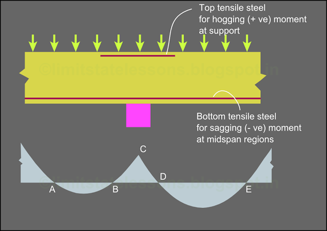
Next we look at a portion of a continuous beam shown in fig.14.8. Here top tensile steel is provided for the hogging moment at the support, and bottom tensile steel is provided for the sagging moment at midspan regions. (A video demonstrating the requirement of top bars at continuous supports can be seen here)

Fig.14.8
Continuous beam carrying UDL

From the bending moment diagram, we can see that the hogging moment progressively decreases on either sides of the support (Value at C decreases towards B on the left side, and towards D on the right side). This indicates that the steel provided for this moment can be curtailed at some distance away from the support. But while doing this curtailment, we must take care of the anchorage requirements beyond the section.

The same is true for the bars provided for the sagging moments also in such continuous beams. As we move from the midspan regions towards either supports, the sagging moment progressively decreases. So here also curtailment can be used for economy, provided anchorage requirements are satisfied.

Yet another point that we have to consider in the above fig. is the bar arrangement related to the points of inflection. In the fig., A,B,D and E are points of inflection. The moments change signs at these points. The bottom steel provided for the region between A and B is not required in the region from B to C, because there, the moment is changing signs from – ve to + ve. But we cannot stop the bars at exact A or B. Anchorage and other requirements like shear, prevention of cracks etc., that are specified by the code should be satisfied.

As mentioned earlier, we will discuss about them as a separate topic ‘curtailment of bars’ in a later section. At present, we have obtained an understanding that anchorage and development length requirements is one of the many important points that have to be considered while finalizing the arrangement of bars in a structural member. We will now focus our attention on the other aspects of bond and development length.

Development length of bundled bars


In the case of bundled bars, the development length required will have a higher value than individual bars. This is because, when bars are bundled together, the area of contact between each bar and the concrete will be reduced. So the grip that concrete exert on the steel will also be reduced. This can be compensated by providing a greater development length, so that more portion of steel will come in contact with the concrete. The quantity by which the length has to be increased is specified by the code:

When two bars are in a bundle: 
• First calculate the Ld for a single bar.
• Then increase this Ld by 10 per cent. That is., new 'increased Ld' = Ld x1.1
• Give this increased Ld for each of the two bars in the bundle.

When three bars are in a bundle:
• First calculate the Ld for a single bar. 
• Then increase this Ld by 20 per cent. That is., new 'increased Ld' = Ld x1.2
• Give this increased Ld for each of the three bars in the bundle.

In a similar way, when there are 4 bars in a bundle, the increase must be 33 per cent. This method of increment can be diagrammatically represented as shown in the fig. below:
Development length for bundled bars
Development length for bundled bars depend on the number of bars in the bundle. Each bar in a bundle should be extended by a certain percentage.

Development length when area of steel provided is greater than area of steel required
As we have seen in the design of beams and slabs, the calculated area cannot be given as such. Bars are available only in certain diameters. We have to choose the proper combination of bar diameters and the number of bars to get the required area. And care should be taken to see that area provided is not less than the area required. This will usually result in an upward rounding. That is., the area provided will usually be greater than area required. In such situations we can provide a modified value of development length denoted as Ldm. The expression for obtaining Ldm  given in clause 25.2.1 of SP 24 is shown below:

Eq.14.7

So we first determine Ld as usual, and multiply it by the ratio (As,required / As,provided).

In the next section we will discuss about bends, hooks etc., that are given to bars for improving anchorage.


NEXT                                          


Copyright©2015 limitstatelessons.blogspot.com - All Rights Reserved