Wednesday, April 29, 2015

Chapter 17 (cont..11)-Solved examples of Two way slabs

We have seen solved example 17.1 in which the design of a two-way slab was illustrated. The four edges of that slab were simply supported. So their corners were free to lift up. If in that problem, there are walls above the supporting walls, or if the edges are built into beams, then it will become a restrained slab. In that case, the design procedure will be different. The corners will not be able to lift up, and we will have to provide corner bars. The design procedure in this case is illustrated in the following solved example:
The reinforcement details according to the above design is shown in the figs.17.40,41,42 and 43 below:
Fig.17.40
Plan view
Reinforcement details of a torsionally restrained two way slab, showing bars in both directions.
Fig.17.41
Section AA
Sectional view showing the reinforcement details of a restrained two way slab.
Fig.17.42
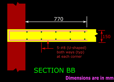
Section BB
Sectional view showing the torsion reinforcements at the corner in a restrained two way slab.
Now we will discuss some features about the above figs.
X direction:
Clear span = 3700mm
Effective span lx = 3826mm
The width of the middle strip in X direction = 0.75 x 3826 = 2869.5 This can be rounded off to the higher value of 2870mm. So the clear span in X direction can be divided as 415 +2870 +415 =3700mm
The point of bent-up is given at 0.15 x3826 =573.9 =574mm
The depth of bend = 150 -20 -4 -20 -4 =102mm. This is shown below in fig.17.43(a)
So the horizontal extension at the top portion from the face of the support = 574 -102 =472
The actual extension required at top portion = 0.1 lx = 0.1 x3826 =382.6.
This is less than 472mm. Hence OK
Fig.17.43
Bent up bar to resist hogging moment at support
Bent up bar should have the required length at the top portion to resist the negative (hogging) moment at support of a two way slab.
Y direction:
Clear span = 4800mm
Effective span ly = 4918mm
The width of the middle strip in X direction = 0.75 x 4918 = 3688.5 This can be rounded off to the higher value of 3690mm. So the clear span in Y direction can be marked off as 555 +3690 +555 =4800mm
The point of bent-up is given at 0.15 x4918 =737.7 =738mm
The depth of bend = 150 -20 -4 -8 -20 -4 =94mm. This is shown in fig.17.43(b)
So the horizontal extension at the top portion from the face of the support = 738 -94 =644
The actual extension required at top portion = 0.1 ly = 0.1 x4918 =491.8
This is less than 644mm. Hence OK
In the next section, we will see the solved example of a two way slab system. Before we see that problem, we have to discuss about fixing the preliminary slab thickness and other parameters like effective spans and effective depths of such a system. We have seen the procedure for a simply supported slab here. There, we multiplied 20 by a factor 1.5. We saw how the factor 1.5 is obtained. Here also, for continuous systems, 1.5 is the same. But 20 has to be replaced by 26. Because 26 is the value of l/d(basic) for continuous systems. This is given in cl.23.2.1 of the code. Details here. So we get:
17.13
d provided ≥  lx/(26 x 1.5).
The effective span of continuous systems should be calculated by using the provisions given in cl.22.2(b) of the code. Details here.
Like for simply supported slabs, here also we have to use a trial and error method to determine the various parameters. This will be illustrated while doing the solved example in the next section.

PREVIOUS      CONTENTS   NEXT

 
             Copyright ©2015 limitstatelessons.blogspot.com - All Rights Reserved

Friday, April 24, 2015

Chapter 17 (cont..10)-Details of Corner bars

'L' Type:
The requirements for this type is given in cl.D-1.8 of the code. We know that corner reinforcements should be provided near both top and bottom surfaces of the slab. Both of them are the same. That is., if we design the reinforcements to be provided near the top surface, the exact same can be provided near the bottom surface also. So we need to discuss about any one, say the one at the top only.
The top one consists of a mesh. A mesh, formed by two layers of bars. The first layer consists of bars parallel to lx. The second layer consists of bars parallel to ly. This second layer is stacked just below the first layer and the two layers are tied together. Thus the mesh is formed. The length of all the bars in both the layers is the same, and should not be less than 1/5 times the smaller side of the slab panel. The smaller side is lx. So length of each bar = 1/5(lx) = 0.2lx.
Now we need to know the number of bars that have to be provided in each direction of the mesh. According to the code, the total number of bars in the X direction in a single mesh should give an area which is not less than 0.75 times Ast,x. Where Ast,x is the area required to resist the maximum bending moment at the midspan. The subscript 'x' is given in Ast,x because we readily know that the maximum bending moment in the midspan will be that in the X (direction of shorter span according to fig.17.1) direction. So Ast,x is the area of steel required to resist the bending moment Mu,x+αx+  wu lx2 . This same number of bars should be given in the Y direction also.
So now we know the details required to make the mesh near the top surface. Another mesh is to be made, which is exactly identical to this. And this second mesh should be placed near the bottom surface, in line with with the top mesh. These two meshes together will satisfy the requirements of torsion reinforcement at the 'L' Type corner. This is shown in the fig. below:
Fig.17.37
Torsion reinforcement at ‘L’ type corner
Reinforcements to resist torsion at a corner of a slab where two edges meet, consists of four layers of bars. Two near top and two near bottom. 
A View showing the bottom mesh at this type of corner in a slab is given in fig.17.38 below:
Fig.17.38
View of bottom mesh
View of bottom mesh at the corner of a torsionally restrained two way slab
We can see that one layer consists of bars parallel to one side of the room, and the second layer consists of bars parallel to the wall which is perpendicular to the first wall. These two layers together form the ‘mesh’. There will be an exactly identical mesh near the top surface of the slab. Thus there will be a total of four layers. The top mesh is not shown in the view above for clarity.
The two meshes can be formed by using ‘U’ bars. This was shown earlier in fig.17.17 and 17.18. A view of this type is shown in the fig.17.39 below:
Fig.17.39
Corner reinforcement using ‘U’ bars
Corner reinforcement using U bars in a torsionally restrained two way slab
'T' Type:
The requirements for this type is given in cl.D-1.9 of the code. The method of making the meshes and placing them in the slab are same as that of the 'L' type. But the required areas of the bars is different. As for the 'L' type, we will discuss all the details:
First we will see the top mesh. This mesh is formed by two layers of bars. The first layer consists of bars parallel to lx. The second layer consists of bars parallel to ly. This second layer is stacked just below the first layer. Thus the mesh is formed. The mesh does not have a 'square' shape. So the length of bars parallel to lx (top layer) is different from the length of the bars parallel to ly (bottom layer). We have to calculate the lengths carefully. From the fig.17.38 below, we can see that at a 'T' type corner, one wall is common to two panels. The bars parallel to lx, provided at this wall extends into both the panels. So these reinforcements should satisfy the requirements of both the panels.
Fig.17.38
Torsion reinforcement at ‘T’ type corner


According to the cl.D-1.8, the bars should extend to a distance of 0.2lx. But in a 'T' type corner, there are two panels, and lx may be different. So in the fig.17.38, we can see that the bars extend for a distance of 0.20lx1 into the upper panel, and a distance of 0.20lx2 into the lower panel. (Both the lengths are measured from the face of the support). This gives the length of the bars in the direction parallel to lx, and thus the length of the mesh can be fixed up. Now we look at the width of the mesh. Unlike the length, the width of the mesh is common to both the panels. That is., once we fix up the width in the direction parallel to ly, it will be applicable to both the panels. So we must take the greater of 0.20lx1 and 0.20lx2 as the width. This is shown in the fig.17.38 above.
Now we need to know the number of bars that have to be provided in each direction of the mesh. According to the code, the total number of bars in the X direction in a single mesh should give an area which is not less than 0.375 times Ast,x (half of that in a 'L' type = 0.5 x 0.75 = 0.375 According to cl.D-1.9) . Where Ast,x is the area required to resist the 'maximum' bending moment at the midspan. The subscript 'x' is given in Ast,x because we readily know that the maximum bending moment in the midspan will be that in the X direction. So Ast,x is the area of steel required to resist the bending moment Mu,x+αx+  wu lx2 . But just as we fixed up the dimensions of the mesh, in fixing up the number and diameter of bars also, we have to take the 'common' factor into consideration. That is., once we fix up the number of bars parallel to lx, they will be common to two panels. So we must take the greater of Ast,x1 and Ast,x2. But while fixing up the number of bars parallel to ly, the 'common' factor does not arise: In the fig.17.38, the bars in the top panel is calculated from 0.375Ast,x1 and the bars in the bottom panel is calculated from 0.375Ast,x2.
So now we know the details required to make the mesh near the top surface. Another mesh is to be made, which is exactly identical to this. And this second mesh should be placed near the bottom surface, in line with with the top mesh. These two meshes together will satisfy the requirements of torsion reinforcement at the 'T' Type corner.
It may be noted that in the figs.17.38, the longer spans of both the upper room and lower room (in the plane of paper) are horizontal, and the shorter sides are vertical. But some times it may so happen that the lower room has it's longer span vertical, and the shorter span horizontal. Part plan of such a situation is shown in fig.17.39 below:
Fig.17.39
Lower room having shorter side horizontal

corner bars at 'T' Type corner in a torsionally restrained two way slab.
The notation for the lower room has changed from lx2 to ly2. But as far as the torsion reinforcements are concerned, the notations used for specifying the dimensions of the meshes, and the quantities of bars in the meshes will not change because, they all depend on the properties of the panels in the X direction only: Dimensions depend on lx values and quantities depend on Ast,x values. However we must thoroughly analyse each structure carefully and find the appropriate values.
In the next section we will see some solved examples that will illustrate the details that we have discussed above.
         Previous                                   CONTENTS                                   Next
             Copyright©2015 limitstatelessons.blogspot.in - All Rights Reserved
 

Friday, April 3, 2015

Chapter 17 (cont..3)- Check for One way shear in a Two way slab

Calculation of one way shear at the supports of a two way slab

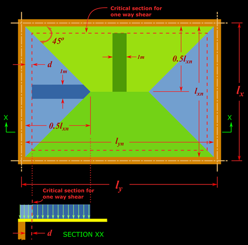
We have seen the procedure for shear check in one way slabs. In one way slabs, the loads are transferred to two opposite walls. If the slab is subjected to uniformly distributed loads, then one half of the load will be transferred to one wall, and the other half will be transferred to the other opposite wall. But in the case of a two way slab, there are four walls, and the loads are transferred to all the four walls. If all these four walls are of equal length, then we can assume that, one fourth of the total uniformly distributed load will be transferred to each wall. But if the lengths are not equal, then the distribution of loads to each wall is complicated. In this situation, we can use the recommendation given by cl.24.5 of the code. According to this clause, the distribution of load on the short side is triangular, and the distribution of load on the long side is trapezoidal. This is shown in the fig.17.6 below:
Fig.17.6
Distribution of load in a two way slab
Right click and select open in new tab for an enlarged view
The portions that each wall will carry can be demarcated by drawing 45o lines from the corners. When these 45o lines are drawn from all the four corners, we will get a triangle (shown in blue color) at each short side, and a trapezium (shown in green color) at each long side. When the area is divided in this manner, the height of the triangles and the height of trapeziums will be the same, and is equal to half of the length of the short side.
We are designing a 1m wide strip of the slab. So the shear force will be maximum when the strips are taken at the apex point of the triangle and the trapezium. We need to consider any one only (triangle or trapezium) because the strip for both the cases are of the same length 0.5 lxn. where lxn is the clear span in the short direction. Also, we need not consider this whole length of 0.5 lxn. Only the load to the right of the critical section (which is at a distance of d, the effective depth of the slab, shown by the red dashed line in plan and section from the face of the support) need to be considered. This is because the shear force at the critical section will be caused by the loads acting on the right side of the section. This is shown in the section XX in the above fig.17.6
The area of the strip to the right side of critical section = (0.5 lxn – d) x 1 = (0.5 lxn – d) m2
So total factored load on this area is obtained as:
Eq.17.12
Vu = wu(0.5 lxn -d)
The rest of the procedure is same as that for a one way slab: The factored shear force Vu should be less than the shear contribution from concrete. The shear contribution from concrete is calculated as kτcbd. Where,
k is the modification factor given in cl.40.2.1.1 of the code, calculation of which we discussed in the case of one way slabs.
τc is the design shear strength of concrete, obtained from table 19 of the code,
b is the width of the strip of slab = 1000 mm, and
d is the average effective depth of the slab = (dx + dy)/2
Thus the procedure for shear check of a two way slab is complete.
Though we have had a somewhat lengthy discussion about the analysis and design of the simply supported two way slab, it can be summarized into just a very few steps:
(a) Determine the preliminary value of total thickness, and effective spans lx and ly as described in the previous section. lx is the shorter span, and ly is the longer span.
(b) Determine the factored load wu [Load factor x (sum of self wt., finishes and LL)]
(c) Calculate r = ly/lx
(d) based on r, calculate αx and αy
(e) Calculate the factored moments  Muxαx wu lx2  , and  Muyαy wu lx2   
(f) Provide the steel determined from Mux in the direction parallel to lx (in the bottom most layer) , and the steel determined from Muy in a direction parallel to ly.
(g) Do the shear check and also all other required checks that we do for a one way slab.
The solved example given below will illustrate all the points that we discussed above:
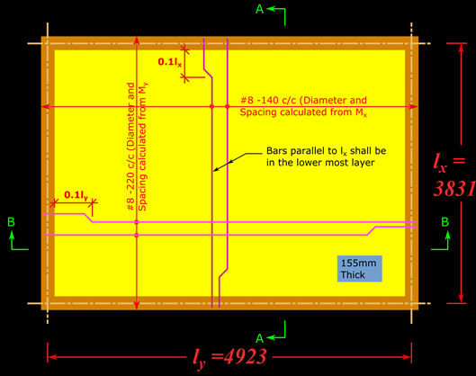
The reinforcement details according to the above design is shown in the figs.17.7,8 and 9 below:
Fig.17.7
Plan view
Plan view showing the reinforcement details of a simply supported two way slab
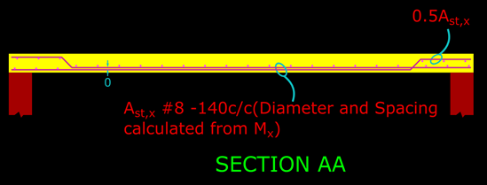
Fig.17.8
Section AA
Sectional view showing the reinforcement details of a simply supported two way slab
Fig.17.9
Section BB
We will now discuss the main features of the above figs:
The steel Ast,x is calculated from Mux. From Ast,x we fixed up #8 bars @ 140 mm c/c. This steel is laid parallel to lx. Consider the set of all the strips parallel to lx. That is., all the blue strips in fig.17.3. The strips in the middle region will require the steel Ast,x. But those on the sides, which are nearer to the shorter walls will be carrying lesser loads, and so they will not require the same Ast,x. For those strips, the spacing can be increased. But, as mentioned earlier, we assume that all the blue strips carry the same load, and so the same steel is provided for all the blue strips. Thus in the above fig.17.7, we can see that #8 @140 mm c/c is provided from the left short wall to the right short wall. Similarly, in the set of red strips parallel to ly in fig. 17.3, the strips nearer to the long walls will not require #8 @ 220mm c/c. For those strips, the spacing can be increased. But we assume that all the red strips carry the same load, and so the same steel is provided for all the red strips. Thus in the above fig.17.7, we can see that #8 @220 mm c/c is provided from the bottom long wall to the top long wall.
Now we will discuss another feature that can be seen in the above figs. Let us consider any one of the blue strips. It is simply supported on the two long walls. So the bending moment at the ends will be zero. So, like any simply supported member, the bending moment varies from a maximum at the middle of the strip to zero at the supports. Thus it is possible to curtail the bars. We have seen the details of curtailment here. For a simply supported two way slab we follow simplified rules of curtailment: The main bars are terminated at alternate ends, at a distance of 0.l from the face of the support. So 50% of the main bars are curtailed, and the other 50% continues into the support. We can see from the fig. that, this type of curtailment is done in both x and y directions.
The curtailed bars are not just stopped at 0.1l from the face of the support. They are given a 45o bend at that point, and thus they become top bars at the support. Thus we will get 50%  Ast as top bars at the supports. These top bars are necessary to resist any hogging moment that may develop at the supports.
In the next section we will see some basic details about torsionally restrained two way slabs.

PREVIOUS      CONTENTS       NEXT

             Copyright ©2015 limitstatelessons.blogspot.com- All Rights Reserved