Showing posts with label Development length for bundled bars. Show all posts

Thursday, January 28, 2016

Chapter 15.15 - Curtailment of Bottom bars when Moment coefficients are used

In the previous section we were discussing the method of curtailment when Moment coefficients are used for the analysis of continuous beams. In this section, we continue the discussion.

We will see an example in which there is a lesser number (3-16#) of top bars at the support. The arrangement is shown in the fig.15.86 below:

Fig.15.86
Arrangement after curtailment

In this case, there are only three bars. Only one of them can be curtailed because two bars have to continue as stirrup hangers. So there will be only one stage of curtailment. The calculations are shown in the fig. below:

Fig.15.87
Calculations of areas after curtailment
Percentage of bars left after curtailment

We can see that the two 16 mm dia. bars give an area of 66.67%. This is greater than the required 60%. So the middle 16 mm bar can be curtailed at 0.15 l1. There is no need to take it upto 0.25 l1. However, the above arrangement should be finalized only after the development length checks using the values of l1 and l2

Let us consider one more example in which 2-16# and 1-20# are given. In this case also, there can be only one stage of curtailment, and that is of the 20 mm dia. bar. The two 16 mm dia. bars have to continue as stirrup hangers. The calculations are given below:

Fig.15.88
Calculations of areas after curtailment

We can see that after curtailment, only 56.14% remains. But we want 60%. So we must extend the bar up to 0.25 l1. In other words, the curtailment should be done only at 0.25 l1. And also, the development length checks should be done using the values of l1 and l2 . The arrangement is shown below:

Fig.15.89
Arrangement after curtailment


So we have completed the discussion about the curtailment of top bars when 'Moment coefficients are used for design of steel'. But in the discussions, we did not consider the case when the end support of the continuous beam is simply supported. In such a support condition, there will not be any bending moment, and the arrangement shown in fig.15.58  that we discussed earlier can be provided.

Now we will discuss about the bottom bars. We know that when Moment coefficients are used, the sagging BM at midspans are also calculated using coefficients. So there will not be any BM diagrams, and we will have to follow the same fig.8.15 of SP 34.

Fig.15.90
Curtailment of bottom bars when Moment coefficients are used

From the fig.15.90, we can see that there is only one stage of curtailment for the bottom bars. The distance of this curtailment is 0.1 l at end supports, and 0.15 l1 at intermediate supports. These distances are measured from the 'imaginary vertical lines within the supports' which mark the effective spans. The area of remaining bars which continue towards the supports is same for both end supports and continuous supports, and is equal to 0.3Ast .

We can work out a quick example to demonstrate the area requirements. Let there be 3-16# as bottom bars in a beam. The middle one can be curtailed. The other two has to continue because, there must be two corner bars at the bottom for the stirrups. So the percentage of 2-16# is equal to 66.67. (calculations are same as that in fig.15.87 above) This is greater than the required 30%.

Let us see another example with 2-16# + 1-20# . The middle 20 mm bar can be curtailed. So the percentage of 2-16# is equal to 56.14. (calculations are same as that in fig.15.88 above) This is greater than the required 30%.

So we will get the curtailment details of ‘bottom bars within the span’ from the above fig.15.90. But we have to work out the following separately:
(i) amount of bottom bars that has to be embedded in the supports.
(ii) length of bottom bars that has to be embedded in the supports.
(iii) Development length requirements for bottom bars at supports.

(i) and (ii) above were discussed before, when we saw the details about cl.26.2.3.3(a) of the code. We saw the figs.15.42 to 15.45 in chapter 15.9, which are based on this clause. So, using those figs., we can calculate (i) and (ii) .

(iii) was also discussed before. The procedure for both simple supports and continuous supports were discussed. MuR is the ‘Ultimate moment of resistance’ of the section, and Vu is the factored shear force at the support. The shear forces are determined by using the coefficients from Table 13. 

Thus we are now in a position to do the curtailment design of a continuous beam when it is designed using ‘Moment coefficients’. The very same procedure can be used also for a continuous slab, when it is designed using moment coefficients. For this we must use fig.9.5 of SP 34.

Curtailment of Bundled bars
When bundled bars are to be curtailed, all the bars in the bundle should not be curtailed at a single section. Each bar must be curtailed at sections which are at least 40Φ apart. This is shown in the fig.15.85 below:

Fig.15.91
Curtailment of individual bars in a bundle

First, the whole bundle is given an extension of La beyond the theoretical cut-off point. Then the individual members of the bundle are curtailed one at a time, and the distance between the sections are greater than or equal to 40Φ. [In the fig., the bars of the bundle are shown separately. This is only for clarity. In actual case, all the bars of a bundle will be in contact]

Another point to note is that while curtailing bundled bars, the bars which are closer to the Neutral axis should be curtailed first. So for a bundled bar at the top of a beam, the bars which are at the bottom in the bundle should be curtailed first. Similarly, for a bundled bar at the bottom of a beam, the bars which are at the top in the bundle should be curtailed first. This is shown in the figs. below:

Fig.15.92
Bundled bar at top of beam section

Fig.15.93
Bundled bar at bottom of beam section

After fixing up the final curtailments, we have to check for development lengths. This is necessary for bundled bars also. We have seen that this check is done based on fig.15.50 (bottom bars) and fig.15.60 (top bars). Now, while checking this for bundled bars, the increased value of Ld should be used based on fig.14.9. This increased value should be available on both sides of a section. 

As an example, let us consider the curtailment involving a bundle of 3 nos. of 12 mm bars. (Assume that the bars are in tension, the bars are of grade Fe 415 deformed steel, and the grade of concrete is M20)  From fig.14.9 we see that Ld of each bar of a bundle of 3 bars should be increased by 20%. We have also seen that for the above assumptions, Ld of 12 mm bars is equal to 564.14 mm. Increasing this by 20%, we get 564.14 x 1.2 = 676.97 = 677 mm. 

• If our bundle belongs to the ‘category of curtailed bars’ in fig.15.50, then the bundle as a whole should have a distance greater than 677 mm on both sides of CL, and then only the curtailment of individual bars can begin. (The individual bars should be curtailed at sections which are more than 40 x 12 = 480 mm apart.)  

• If it belongs to the ‘category of continuing bars’, then the distance on both sides of the theoretical cut-off section should be greater than 677 mm. These requirements are shown in the figs. below:

Fig.15.94
Development length requirements of a 'curtailed' bundled bar

Fig.15.95
Development length requirements of a 'continuing' bundled bar


In fig.18.94, the diameter of the curtailed bar should be used in the calculation of La.

So we have completed the discussion about the curtailment of bars. We will see some solved examples.

Solved example 15.1
In this example we will design the curtailment and layout of the bars of the beam that we designed in solved example 4.3

In that example, the final section was designed. Now, The design of curtailment and layout is given now as the Solved example 15.1

Solved example 15.2
In this example we will do the ‘shear design’ of the beam that we designed just above in solved example 15.1. While doing this, we will be considering the points that have to be checked while doing the shear design of a beam in which curtailment of tensile bars have been done. 

In the next chapter we will discuss about the design of Stairs.

PREVIOUS       CONTENTS       NEXT                                          

Copyright©2016 limitstatelessons.blogspot.com - All Rights Reserved

Saturday, December 12, 2015

Chapter 14 (cont..1) - Situations which demand Development length and Anchorage

In the previous section we discussed about the bond stress between concrete and steel. We saw the importance of providing the required development length. We did our discussions based on a cantilever beam. Now we will see some other situations.

Consider a doubly reinforced cantilever beam as shown in fig.14.5 below:

Load applied on a doubly reinforced cantilever beam
In doubly reinforced cantilever beams, the bottom bars will be in compression, and so enough anchorage length should be provided to resist the pushing in of the bar.

In the previous section, we have seen how the top steel in the above beam can be made safe from being pulled out. Now we will see the bottom steel. The bottom steel is in compression. So they will be pushed in. The concrete should have sufficient grip on the bar for preventing this from happening. For this, there should be sufficient embedded length. Here the required embedment is the Ld for compression steel. We can calculate it using the same Eq.14.6 used for tension steel. The only difference is that, if deformed bars are being used, we must increase the bond stress in table 14.1, first by 60 per cent, and then by 25 per cent.

Next we consider a situation encountered in a simply supported beam. Fig.14.6 shows the region near the left support of a simply supported beam carrying a UDL. The bending moment diagram is also shown.

Fig.14.6
Simply supported beam carrying a  UDL

The beam is reinforced with 2 types of bars – bar 'a' and bar 'b' . Bar 'a' continues uninterrupted from one support to other. But bar 'b' is curtailed at section AA. This is because the bending moment is decreasing progressively towards the support, and so all the bars provided near the midspan region need not be provided at the regions near supports. We can find the section AA beyond which bar 'b' is no longer required. We will discuss the method to determine the position of AA in a later section. At present we are more concerned about another matter: 

We cannot cut off the bar 'b' at the exact section AA as shown in the above fig. The reason is as follows: We know that bar 'b' is carrying tensile loads. That means it is being stretched. So it will have a tendency to regain it's original length, and so it will try to shorten. It will try to shorten back to it's original length. If this shortening happens, it will mean that the end of the bar is moving away from section AA, towards the mid span region of the beam. So the bar will no longer be available at AA. To prevent this from happening, we must extend the bar 'b' even beyond AA to a certain distance as shown in fig.14.7 below. This distance should be such that, it is sufficient for the concrete to exert the required grip on the bar, to prevent it from shortening back to it's original length. In other words, the bar 'b' must be given sufficient ‘anchorage’ beyond section AA.

Fig.14.7
Extension of the bar
Anchorage requirement beyond point of curtailment

Curtailment of bar is done for economy in the design. In addition to the above discussed points, some other aspects also have to be considered while doing bar curtailment. So we will discuss about them as a separate topic in a later section.

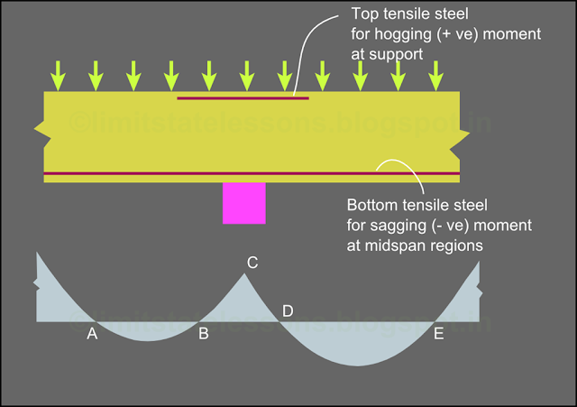
Next we look at a portion of a continuous beam shown in fig.14.8. Here top tensile steel is provided for the hogging moment at the support, and bottom tensile steel is provided for the sagging moment at midspan regions. (A video demonstrating the requirement of top bars at continuous supports can be seen here)

Fig.14.8
Continuous beam carrying UDL

From the bending moment diagram, we can see that the hogging moment progressively decreases on either sides of the support (Value at C decreases towards B on the left side, and towards D on the right side). This indicates that the steel provided for this moment can be curtailed at some distance away from the support. But while doing this curtailment, we must take care of the anchorage requirements beyond the section.

The same is true for the bars provided for the sagging moments also in such continuous beams. As we move from the midspan regions towards either supports, the sagging moment progressively decreases. So here also curtailment can be used for economy, provided anchorage requirements are satisfied.

Yet another point that we have to consider in the above fig. is the bar arrangement related to the points of inflection. In the fig., A,B,D and E are points of inflection. The moments change signs at these points. The bottom steel provided for the region between A and B is not required in the region from B to C, because there, the moment is changing signs from – ve to + ve. But we cannot stop the bars at exact A or B. Anchorage and other requirements like shear, prevention of cracks etc., that are specified by the code should be satisfied.

As mentioned earlier, we will discuss about them as a separate topic ‘curtailment of bars’ in a later section. At present, we have obtained an understanding that anchorage and development length requirements is one of the many important points that have to be considered while finalizing the arrangement of bars in a structural member. We will now focus our attention on the other aspects of bond and development length.

Development length of bundled bars


In the case of bundled bars, the development length required will have a higher value than individual bars. This is because, when bars are bundled together, the area of contact between each bar and the concrete will be reduced. So the grip that concrete exert on the steel will also be reduced. This can be compensated by providing a greater development length, so that more portion of steel will come in contact with the concrete. The quantity by which the length has to be increased is specified by the code:

When two bars are in a bundle: 
• First calculate the Ld for a single bar.
• Then increase this Ld by 10 per cent. That is., new 'increased Ld' = Ld x1.1
• Give this increased Ld for each of the two bars in the bundle.

When three bars are in a bundle:
• First calculate the Ld for a single bar. 
• Then increase this Ld by 20 per cent. That is., new 'increased Ld' = Ld x1.2
• Give this increased Ld for each of the three bars in the bundle.

In a similar way, when there are 4 bars in a bundle, the increase must be 33 per cent. This method of increment can be diagrammatically represented as shown in the fig. below:
Development length for bundled bars
Development length for bundled bars depend on the number of bars in the bundle. Each bar in a bundle should be extended by a certain percentage.

Development length when area of steel provided is greater than area of steel required
As we have seen in the design of beams and slabs, the calculated area cannot be given as such. Bars are available only in certain diameters. We have to choose the proper combination of bar diameters and the number of bars to get the required area. And care should be taken to see that area provided is not less than the area required. This will usually result in an upward rounding. That is., the area provided will usually be greater than area required. In such situations we can provide a modified value of development length denoted as Ldm. The expression for obtaining Ldm  given in clause 25.2.1 of SP 24 is shown below:

Eq.14.7

So we first determine Ld as usual, and multiply it by the ratio (As,required / As,provided).

In the next section we will discuss about bends, hooks etc., that are given to bars for improving anchorage.


NEXT                                          


Copyright©2015 limitstatelessons.blogspot.com - All Rights Reserved