Showing posts with label Staircases. Show all posts

Friday, February 5, 2016

Chapter 16.1 - Effective span of stairs

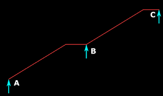
In the previous section we saw the support A of the stair. Now we will see the other supports. End B of flight AB is resting on a masonry wall. This is similar to an ordinary horizontal slab resting on a masonry wall, and is treated as a simple support. In the same way, the end C of flight CD, which is resting on the same wall, is also a simple support.

Now we consider end D. It is resting on a reinforced concrete beam. This beam is a part of the main building. It should have adequate support from the main building. It should also be properly restrained against rotation and/or over turning. Stability of this beam should be ensured while the design and construction of the Main building itself. When the end D of the stair rests on the beam, some extra bars are provided which will properly anchor the stair onto the beam.  These bars are provided only to prevent the sliding of the flight CD. They do not resist any bending moment. Considering the above points, The support D is also considered as a Simple support.

So we can modify fig.16.6 by adding the support conditions. This is shown in the fig.16.8 below:

Fig.16.8
Supports of stair flights

So we have fixed up all the supports for the stair.

At this time we will take a quick look at another type of support commonly seen in practice. That is., the 'continuous support'. An example of this is shown in the fig.16.9 below:

Fig.16.9
Example of a continuous support for stairs
An intermediate continuous support for a stair

ABC is a stair. It consists of two flights AB and BC. But we cannot separate the two flights. The whole stair ABC should be analysed as a single unit. Support B should be treated as a 'continuous support'. A continuous support can come within a single flight also as shown in fig.16.10 below. Here the flight AB has a larger span. So it is economical to provide an intermediate support C. It should be noted that hogging moments will be produced at these intermediate supports. So top steel will have to be provided. A video of a small scale experiment, showing the behaviour of continuous systems can be seen here.

Fig.16.10
Example of a continuous support within a single flight


Effective span of stairs
Based on cl.33.1(a) of the code, the effective span l of the slabs in our case is equal to the centre to centre distance between the walls/beams. This distance is measured along the horizontal direction. We need not measure it from the centre of one support to the centre of the other, along the slope of the slab. The method of measurement is shown in the fig.16.11 below:

Fig.16.11
Effective span of stairs
Method of measuring the effective span of stairs in the horizontal direction

Our stair falls within the category of sub clause (a) because it is supported on walls/beams parallel to the risers.  The sub clauses (b) and (c) of cl.33.1 gives us the method of calculating the effective span of some other types of stairs. We will discuss about them in later sections. Later, we will also see the stairs supported on walls/beams perpendicular to the risers.

For the stairs of type which span between walls/beams parallel to risers, for a preliminary design, the thickness of waist slab can be taken as l/20. If it is a continuous type of stair as shown in fig.16.9 and 16.10, then a lesser thickness  l/25 can be used. Where 'l' is the effective span.

Arrangement of steps and landings
In most cases the arrangements of steps and landings will be given in the architectural drawings. The structural designer will then have to fix up the thickness of waist slab, the arrangement of reinforcements, grade of concrete etc., But in some drawings, only the space available, and a preliminary design of stairs will be given. We will then have to design all other details. Let us see how the design in our example (fig.16.3 of the previous section) was finalised.

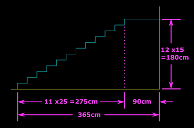
The total height that the stair has to climb is the vertical distance between the ground surface and the top of the roof slab. This is equal to 315 +45 = 360cm. If we provide two flights, the height that each flight has to climb is equal to 360/2 = 180cm. Assuming the Rise R = 15cm, the no. of Risers required for each flight = 180/15 = 12 Nos. For N Risers, there will be (N-1) Treads. So for our case, there will be 11 Treads. Assuming Tread T= 25cm, the 11 Treads will take up a length of 11 x25 = 275cm. Adding 90cm landing to this, we get 365 cm. So we can begin to draw the first riser from a point which is 365 cm from the rear end of the building. This is a vertical line 15 cm in length. It should be drawn upwards from the surface of the ground. From the top point of the first riser, a horizontal line 25 cm in length is drawn. This is the first Tread. From the end point of this line, the second riser is drawn vertically upwards. In this way, all the steps of the flight can be drawn.  This is shown in the fig.16.12 below:

Fig.16.12
Outline of Risers and Treads of the first flight

Next we draw two more lines in the above diagram. The first line is the one which joins the bottom points of all risers. The second line is drawn parallel to the first line, below it, at a distance of 't' from it. Note that 't' should be measured in an exact perpendicular direction to the first line. This is shown in the fig. below:

Fig.16.13
Drawing the waist slab

The second line, upon reaching the landing will deviate, and become horizontal. It then runs parallel to the top surface of the landing at a distance of ‘t’ from it. This second line indicates the under surface of the flight.

It is clear that, in order to draw the bottom parallel line in the above fig.16.13, we must have the value of 't'. Let us see how it is calculated for the two flights. For this, we must refer figs.16.3 and 16.4. From these figs., we will get the total length of each flight and the widths of supports.

• The first flight has a total length of 365cm. The width of bottom support is 25cm and the width of top support (masonry wall) is 20cm. So the effective span = 365 -(25/2) -(20/2) = 342.5 cm
• The second flight has a total length of 90 +(11 x25) +90 = 455 cm. The width of both the supports are 20cm. So the effective span = 455 -20 =435cm.
• The second flight has more effective span. So we will calculate 't' based on it. Thus t = 435/20 = 21.75 cm.
• This can be rounded off to 22cm thickness. For uniformity, this thickness should be provided for both the flights.
In the next section we will discuss about the 'calculation of loads' on stairs.

PREVIOUS       CONTENTS       NEXT                                        


                            Copyright©2016 limitstatelessons.blogspot.in - All Rights Reserved

Monday, February 1, 2016

Chapter 16 - Introduction to Staircases

In the previous section we completed the discussion on curtailment of bars. In this section we will discuss the design of staircases.

Stairs is an important part of the building. It is one of the means of access between various floors. Fig.16.1 given below shows the view of an external stair of a small single storey building. It is used for giving access to the terrace of the building.

Fig.16.1
View of a stair
External staircase in a residential building

In the above fig., the stair portion is shown at a condition before finishing works like plastering, painting, side railings etc., are done on it. This is to show the structural details. We can see that: 
• The stair begins with an inclined slab from the ground surface. This inclined slab becomes horizontal towards the end, and finds support on a masonry wall. 
• Then the stair changes direction. In the new direction, first there is a horizontal portion. Then the inclination begins. Towards the end, it becomes horizontal again and finds support on a beam, which is projecting out from the main building. 
• At this end point, the stair has reached the terrace of the building. 

The view from the rear side of the stair is shown below in fig.16.2.

Fig.16.2
View from rear side

In the two views, we can see that in the inclined portions, steps are made in brick masonry. These steps makes the upward and downward movement easier. No such masonry work is required over the horizontal portions of the slabs. To show more technical details of a stair, we need to draw elevation and plan views. These drawings related to the above stair, are given in the figs. 16.3 and 16.4 below:

Fig.16.3
Side elevation of Stair
Side elevation of stairs gives it's details like Rise, Tread, landing width

Fig.16.4
Plan of Stair
Plan view of a staircase gives details about Going

In the above elevation and plan views, the reinforced concrete slabs are shown in yellow colour, and the steps made in masonry work are shown in blue colour. 
• The measurement of the horizontal top portion of a step is called  Tread, denoted by the letter 'T'. 
• The vertical distance between two adjacent treads is called  Rise denoted by the letter 'R'. 
Generally, a value of 30 mm is given for T and 15 mm is given for R, in public buildings. But for residential buildings, lower values can be used.

It may be noted that T can be given a small increase when the finishing works are applied to the steps. This increase is obtained by a projection (called  Nosing) beyond the vertical face of the step. An example is shown below:
Fig.16.5
Nosing given to steps

In the above fig., the vertical piece of tile will not help in increasing T because, it will be coming in all steps. The horizontal piece of tile is given a projection beyond the vertical piece.

The width of stairs vary from 1.1 m to 1.6 m. Larger widths are given for stairs of public buildings. Stairs in residential buildings can be of lower widths. But they should not be less than 85 cm. In the above plan view, the width is shown as 90 cm. The horizontal portion of the stair is called the Landing. The horizontal distance between the first and last risers is called the Going. In the above elevation and plan views, we can see that, the length of the intermediate landing is 180 cm. It's width is 90 cm.

• On the side of the first flight, the last masonry step of this flight is contributing 25 cm for making up the required width of 90 cm for the intermediate landing. This is because, the horizontal portion of the concrete slab has a width of only 65 cm on the side of the first flight.
• But on the side of the second flight, the horizontal portion of the concrete slab readily have a width of 90 cm. So no contribution is required from the masonry steps.
• At the top most landing also, the contribution is made by the last masonry step. 

Stairs can be considered to consist of Flights. In the above plan view, there are two flights. Flight AB and Flight CD. AB has one Going and one Landing. CD has one Going and two landings. The number of steps in a flight should not exceed 12. After 12 steps, there must be a Landing.

Supports of Stairs
Now we will discuss about the supports that are given to the above stair. First of all, we must consider the two flights separately. This can be explained as follows: At the intermediate landing, the two flights are connected together. But as we will soon see in the ‘design of reinforcements for the stairs’, the main bars of the two flights are not connected together. Only the distributor bars in the intermediate landing will be common to the two flights. So there is no transfer of force between the two flights. In other words, the loads and forces in one flight will not have any effect on the other flight. So we can draw the line diagram of the two flights separately as shown in the fig.16.6 below:

Fig.16.6
Line diagram of Stairs

We are able to separate the individual flights of the above stairs  easily. For stairs of other shapes, care should be taken while separating the flights. Now we will see the support at A. In the elevation shown in fig.16.3, we can see that the inclined slab rests directly on the ground. But at the point of contact with the ground, the slab is given an increased thickness as shown in the fig. below:

Fig.16.7
Increased thickness at support

The increase in thickness is given in such a way that the resulting enlarged portion will become the first step. The extra portions are shown in red color. We can see that there is one large red triangle above and a small red triangle below the slab. The larger triangle has the same size as the steps. The increase is achieved not only by providing more concrete. The reinforcement of the slab is also bent in such a way as to get this final shape. We will discuss about it in the section on reinforcements of stairs. This method gives a good seating for the slab. Appropriate foundation is provided below this enlarged portion. Extra bars are  provided in the foundation, which will be bent into the inclined slab of the stair. This will prevent sliding of the inclined slab.


This type of arrangement gives a 'Simple support' at A. In the next section we will discuss about the other supports at B, C and D.

PREVIOUS       CONTENTS       NEXT                                          


Copyright©2016 limitstatelessons.blogspot.in - All Rights Reserved