Towards the end of the previous section we saw that the supports provided to the flights of the stair is unclear from the plan and sectional views. To get a clear picture of how the flights are supported, we will now see some 3D views of the building. The direction of views can be understood from the 'North direction' which is indicated in the key plan given in the previous section.
Fig.16.36
View from South East

Fig.16.37
View from North East

Fig.16.38
View from North West

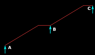
We can see that, two brick walls are built, one on Bm1 and the other on Bm5. The brick wall over Bm5 can be seen in the sectional view that we saw earlier in fig.16.35. These two walls are parallel. The intermediate landing is supported by these two walls. That is., the intermediate landing is a one-way slab, spanning between these two walls. So at B, the flight AB can rest on this landing. In the same way, at C, the flight CD can also rest on this landing. Thus there is no need to take the flights up to Bm 3 at the rear of the building.
What about the supports at A and D? We can see that at A, there is a landing (at Floor1 level) in between Bm1 and Bm5. This landing is designed as a one-way slab spanning between these two beams. Then, the flight AB is supported on this landing at A.
There is an exact duplicate of this landing, directly above it (at Floor2 level). It spans between Bm1 and Bm5. Flight CD is supported at D on this landing. Thus there is no need to take the flights up to Bm 4 in the front of the building.
So we can summarize the support details as follows:
Flight AB is supported between two landings. One landing at A and another landing at B
The landing at A is at level 1. It is a one way slab spanning between Bm1 and Bm5
The landing at B is the intermediate landing of the stair. It is a one way slab spanning between walls built over Bm1 and Bm5
Flight CD is supported between two landings. One landing at C and another landing at D
The landing at C is the same intermediate landing on which end B of the first flight AB is supported
The landing at D is at level 2 It is a one way slab spanning between Bm1 and Bm5. This landing is an exact duplicate of the landing at A of the first flight.
It must be noted that in this type of stairs, special care should be taken while fixing up the arrangement and position of bars of both the sloping portions and the landings. We will see the details about it when we design the reinforcements of this type of stairs.
From the above discussion, it is clear how flights are supported on landings. The whole width of the landing slabs (1.2m in our case) is taking part in supporting the flights. But when we calculate the effective span of the flight, we can consider only a certain portion of the width. To determine this width, we will use the diagram shown below:
Fig.16.39
Portions of landings that can be considered for calculating Effective span

The width of the first landing is 2X and that of the second landing is 2Y. (Here X and Y are in m). Such a notation using 'twice X and Y' is only for the ease of presenting the formula. The widths need not be exact multiples of 2. It only implies that, whatever be the widths of the landings, half of those widths should be used for the calculations. (The hatched portions shows the support available for the landing slabs. These portions are not of any significance in our present discussion about effective span). The steps involved in the calculations are as shown below:
Step 1:
Determine X, half the width of the first landing.
Then, a certain length (denoted as 'Quantity 1') is determined as follows:
IF X is less than 1 m, THEN, Quantity 1 = X
IF X is greater than 1 m, THEN, Quantity 1 = 1 m
This simply means that Quantity 1 = the lesser of {X ; 1 m}. It can be presented in a graphical form as shown below:

Step 2:
Determine G, the Going.
Let Quantity 2 = G
Step 3:
Determine Y, half the width of the second landing.
Then, a certain length (denoted as 'Quantity 3') is determined as follows:
IF Y is less than 1 m, THEN, Quantity 3 = Y
IF Y is greater than 1 m, THEN, Quantity 3 = 1 m
This simply means that Quantity 3 = the lesser of {Y ; 1m}
Step 4:
This is the final step in which we just add the above three lengths. The sum thus obtained is the effective span. Thus:
Eq.16.17
Effective span = Quantity 1 + Quantity 2 + Quantity 3
From the method of calculation of Quantity 1 and Quantity 3, we can say that,
only half the width of a landing can become part of the effective span.
Also, if this half width is greater than 1m, then, only 1m can become part of the effective span.
If we analyse the above calculations, we can obtain one more inference:
Eq.16.18
If width of each of the two landings is less than 2m, then, we can calculate the effective span directly as:
Effective span = c/c distance between the landings.
So we can add these details to the above fig.16.39, and modify it as shown below:Fig.16.40
Effective span of flights supported on Landing slabs

Load calculations
The design of this type of stair has two parts.
In the first part, we design the flight which has an effective span obtained using 16.17.
But this flight has to be provided with adequate support on the landing slabs. So the design of landings is done as the second part.
So we will do the calculations of the loads also in two parts. In part 1, we will calculate the loads on the flight, and in part 2, we will calculate the loads on the landing.
Part 1: Loads on the flight.
From the fig.16.40 above, we can see that when we determine the effective span of the flight, we are getting a line diagram with two landings of lengths l2 and l3 , and a Going with length l1 . This is same as the line diagram (fig.16.21) of an ordinary longitudinal stair supported on walls or beams, that we saw at the beginning of the chapter.
So the methods for load calculations are also the same:
• The sloping portion has 4 load components which make up w1 (Eq.16.9),
• and the landing portions have 3 load components which make up w2 (Eq.16.10).
Thus we can easily compute w1 on the sloping portion and w2 on the landing portions. [It may be noted that even if the flight is not symmetrical (the widths of landings not being equal), w2 will be the same on both the landings, as w2 is the load per unit area. But for this, both the landings should have the same thickness.]
After computing w1 and w2, a modification has to be applied to w2. Recall that a modification to w2 was made in the case of 'stairs at right angles' which we saw in the previous section. Here also the modification is required because, w2 is resisted by both landing and the flight. But there is an important difference. It can be explained on the basis of the following fig:
 Fig(a) shows the landing of a right angled stair and Fig(b) shows the flights supported on landings. Consider the upper flight in (b).
• The load w2 on the landing will contribute towards the bending of this flight.
• The load w2 will cause the bending of the landing also.
• So some portion of w2 is resisted by the flight and the remaining portion is resisted by the landing.
• But the portion resisted by the flight will 'come back on the landing' because, the landing itself is a support for the flight.
• This is different from the situation in fig(a), in which the flight is not supported on the landing, but on a separate wall or beam.
■ As the 'portion of w2 resisted by the flight', comes back to the landing, no reduction should be applied to w2 while analysing the landing.
■ A reduction of 0.5 can be applied to w2 while analysing the flight because, the flight will not be resisting a full w2.
Fig.16.36
View from South East
Fig.16.37
View from North East
Fig.16.38
View from North West
We can see that, two brick walls are built, one on Bm1 and the other on Bm5. The brick wall over Bm5 can be seen in the sectional view that we saw earlier in fig.16.35. These two walls are parallel. The intermediate landing is supported by these two walls. That is., the intermediate landing is a one-way slab, spanning between these two walls. So at B, the flight AB can rest on this landing. In the same way, at C, the flight CD can also rest on this landing. Thus there is no need to take the flights up to Bm 3 at the rear of the building.
What about the supports at A and D? We can see that at A, there is a landing (at Floor1 level) in between Bm1 and Bm5. This landing is designed as a one-way slab spanning between these two beams. Then, the flight AB is supported on this landing at A.
There is an exact duplicate of this landing, directly above it (at Floor2 level). It spans between Bm1 and Bm5. Flight CD is supported at D on this landing. Thus there is no need to take the flights up to Bm 4 in the front of the building.
So we can summarize the support details as follows:
Flight AB is supported between two landings. One landing at A and another landing at B
The landing at A is at level 1. It is a one way slab spanning between Bm1 and Bm5
The landing at B is the intermediate landing of the stair. It is a one way slab spanning between walls built over Bm1 and Bm5
Flight CD is supported between two landings. One landing at C and another landing at D
The landing at C is the same intermediate landing on which end B of the first flight AB is supported
The landing at D is at level 2 It is a one way slab spanning between Bm1 and Bm5. This landing is an exact duplicate of the landing at A of the first flight.
It must be noted that in this type of stairs, special care should be taken while fixing up the arrangement and position of bars of both the sloping portions and the landings. We will see the details about it when we design the reinforcements of this type of stairs.
From the above discussion, it is clear how flights are supported on landings. The whole width of the landing slabs (1.2m in our case) is taking part in supporting the flights. But when we calculate the effective span of the flight, we can consider only a certain portion of the width. To determine this width, we will use the diagram shown below:
Fig.16.39
Portions of landings that can be considered for calculating Effective span
The width of the first landing is 2X and that of the second landing is 2Y. (Here X and Y are in m). Such a notation using 'twice X and Y' is only for the ease of presenting the formula. The widths need not be exact multiples of 2. It only implies that, whatever be the widths of the landings, half of those widths should be used for the calculations. (The hatched portions shows the support available for the landing slabs. These portions are not of any significance in our present discussion about effective span). The steps involved in the calculations are as shown below:
Step 1:
Determine X, half the width of the first landing.
Then, a certain length (denoted as 'Quantity 1') is determined as follows:
IF X is less than 1 m, THEN, Quantity 1 = X
IF X is greater than 1 m, THEN, Quantity 1 = 1 m
This simply means that Quantity 1 = the lesser of {X ; 1 m}. It can be presented in a graphical form as shown below:

Step 2:
Determine G, the Going.
Let Quantity 2 = G
Step 3:
Determine Y, half the width of the second landing.
Then, a certain length (denoted as 'Quantity 3') is determined as follows:
IF Y is less than 1 m, THEN, Quantity 3 = Y
IF Y is greater than 1 m, THEN, Quantity 3 = 1 m
This simply means that Quantity 3 = the lesser of {Y ; 1m}
Step 4:
This is the final step in which we just add the above three lengths. The sum thus obtained is the effective span. Thus:
Eq.16.17
Effective span = Quantity 1 + Quantity 2 + Quantity 3
From the method of calculation of Quantity 1 and Quantity 3, we can say that,
only half the width of a landing can become part of the effective span.
Also, if this half width is greater than 1m, then, only 1m can become part of the effective span.
If we analyse the above calculations, we can obtain one more inference:
Eq.16.18
If width of each of the two landings is less than 2m, then, we can calculate the effective span directly as:
Effective span = c/c distance between the landings.
So we can add these details to the above fig.16.39, and modify it as shown below:Fig.16.40
Effective span of flights supported on Landing slabs
Load calculations
The design of this type of stair has two parts.
In the first part, we design the flight which has an effective span obtained using 16.17.
But this flight has to be provided with adequate support on the landing slabs. So the design of landings is done as the second part.
So we will do the calculations of the loads also in two parts. In part 1, we will calculate the loads on the flight, and in part 2, we will calculate the loads on the landing.
Part 1: Loads on the flight.
From the fig.16.40 above, we can see that when we determine the effective span of the flight, we are getting a line diagram with two landings of lengths l2 and l3 , and a Going with length l1 . This is same as the line diagram (fig.16.21) of an ordinary longitudinal stair supported on walls or beams, that we saw at the beginning of the chapter.
So the methods for load calculations are also the same:
• The sloping portion has 4 load components which make up w1 (Eq.16.9),
• and the landing portions have 3 load components which make up w2 (Eq.16.10).
Thus we can easily compute w1 on the sloping portion and w2 on the landing portions. [It may be noted that even if the flight is not symmetrical (the widths of landings not being equal), w2 will be the same on both the landings, as w2 is the load per unit area. But for this, both the landings should have the same thickness.]
After computing w1 and w2, a modification has to be applied to w2. Recall that a modification to w2 was made in the case of 'stairs at right angles' which we saw in the previous section. Here also the modification is required because, w2 is resisted by both landing and the flight. But there is an important difference. It can be explained on the basis of the following fig:

• The load w2 on the landing will contribute towards the bending of this flight.
• The load w2 will cause the bending of the landing also.
• So some portion of w2 is resisted by the flight and the remaining portion is resisted by the landing.
• But the portion resisted by the flight will 'come back on the landing' because, the landing itself is a support for the flight.
• This is different from the situation in fig(a), in which the flight is not supported on the landing, but on a separate wall or beam.
■ As the 'portion of w2 resisted by the flight', comes back to the landing, no reduction should be applied to w2 while analysing the landing.
■ A reduction of 0.5 can be applied to w2 while analysing the flight because, the flight will not be resisting a full w2.
With this modification applied, part 1, the load calculation on flight is complete. When those loads are calculated, we can find the moments and reactions. If the flight is symmetrical, we can use the same equations Eq.16.15 and 16.16 (which we derived for simple longitudinal stairs) to find the reactions and the moments. In the next section, we will see part 2, the load calculation on landing.