Sunday, March 8, 2015

Chapter 16.13 - Stairs cantilevering on the sides of Stringer beam

In the previous section we saw the details of transverse stairs which cantilever from the side of a stringer beam.  The following solved example illustrates the design of  such a stair.
The reinforcement details according to the above solved example is shown in the figs.16.81, 82 and 83 given below. The cantilever waist slab has to be properly anchored into the beam. For this, the stirrups of the beam are extended into the slab as shown below in fig 16.81:
Fig.16.81
Extending the stirrups into the slab
stirrups which enclose the main bars of the beam, are extended into the slab so that the slab will be properly anchored into the beam.
When such an arrangement is given, we must take care of the diameter of bars and the spacing requirements. The spacing of the main bars of the slab will be the same as the spacing of the stirrups. So the stirrups of the beam should be having a uniform spacing throughout it's length. And for our case, this spacing should not be greater than 250mm c/c, and the diameter should not be less than 10mm.
If the spacing of 10mm dia. stirrups required for the beam is less than 250mm c/c, then the spacing of bars in the slab will also become less than 250mm c/c. In that case check should be done to ensure that pt is less than pt,lim. Other wise, the slab will become over reinforced.
The elevation and sectional views are given below:
Fig.16.82
Sectional elevation
Sectional elevation of a transverse staircase cantilevering from one side of a stringer beam


Fig.16.83
Section XX
Section showing reinforcement details of a transverse staircase cantilevering from one side of a stringer beam.
Now we will discuss some more features of the above figs: In cantilever members, the main tensile steel is given at the top. So in our case, the main bars are given as the top most layer. The distributor bars are given as the second layer from the top. This arrangement will give maximum possible effective depth ‘d’ for the section. So while bending the bars for the stirrups of the beam at the site, care should be taken to see that the extension given to the stirrup will be at the exact required level in the slab. A bar bending schedule should be prepared to give the exact measurements.
As the slab has a thickness of 110mm, a bottom layer consisting of #8 bars at 250mm c/c should be given. This is indicated by the green bars in section XX. In this layer, alternate bars should be given two 90 degree bends at the end. This is for tying them with the top layer. This bottom layer is not shown in the sectional elevation in fig.16.82.

Transverse stairs cantilevering from both sides of a stringer beam:


The following fig. 16.84 shows the part view of a stair
Fig.16.84
Part view of a stair
Part view of a stair cantilevering from both sides of a stringer beam. 
The waist slab is cantilevering on both sides of the stringer beam. The load calculation procedure is same as that of the other types of transverse stairs that we saw before. So we can use the same Eq.16.25 for the calculation of the loads. From this eq., we will get w1 , the load per 1m length, on a 1m wide strip. If the cantilevering length on both the sides are equal, we need to do the design of only one side as shown in the line diagram below:
Fig.16.85
Line diagram for stairs cantilevering on both sides of a stringer beam
The effective span l of the cantilever (cl.22.2.c) is the length of the cantilever up to the face of the support plus half the effective depth. For initial proportioning, we can assume the thickness of waist slab to be clear length of cantilever/5 . However, this should be finalized only after the complete design and various checks.

In the next section, we will see a solved example of the above type of stairs.

PREVIOUS     CONTENTS       NEXT                                        

                            Copyright©2016 limitstatelessons.blogspot.com - All Rights Reserved

Thursday, March 5, 2015

Chapter 16 (cont..12)

The following solved example illustrates the design of a transverse stair.
The reinforcement details according to the above solved example is shown in the figs.16.64 and 16.65 given below:
Fig.16.64
Sectional elevation of transverse stair
Sectional elevation showing the reinforcement details of a transverse staircase supported on two stringer beams
Fig.16.65
Section XX
Section showing the reinforcement details of a transverse staircase supported on two stringer beams.
We will now discuss the various features of the above two figs:
The main bars are given as the bottom most layer. The distributor bars are given as the second layer from the bottom. This arrangement will give maximum possible effective depth ‘d’ for the section. From the section XX, we can see that the main bars are given two 90o bends at both the ends. This will give a 'hook' like arrangement at both ends. The top portion of these 'hooks' will act as the steel required for resisting any possible hogging moment at the supports. The length required for this top steel is 0.15l, where l is the effective span of the waist slab. But the area required for this top steel is only half of that at the mid span. So, as shown in the inset, only alternate bars are given these hooks.
The distributor bars are of mild steel. So the symbol Φ is given to denote them.
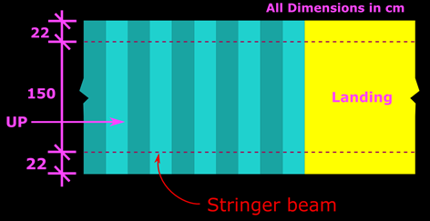
In the above example, only a part plan (shown in the fig.16.65 below) of the stair was given along with the problem data.
Fig.16.65
Problem data of solved example 16.3
This is because, this small portion is sufficient for defining the problem of this type of a transverse stair. Some times this stair may have a landing also as shown below.
Fig.16.66
Landing in a transverse stair
In this case also the sloping portion can be analysed and designed by the same procedure, and the landing can be analysed and designed as a simply supported one-way slab.

Stairs cantilevering from the side of a beam:

The following fig.16.67 shows the part view of a stair.
Fig.16.67
View of a cantilever stair
It is projecting from the side of a wall. The wall is shown in a finished state. So we cannot see more details. The fig. below shows the view before the plastering is applied to the wall.
Fig.16.68
View of a stair cantilevering from a stringer beam
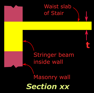
We can see that the stair is projecting from the side of a beam, which is concealed inside the wall. In actual construction, the beam (which frames into columns) and the waist slab will be cast first, and after curing and removal of form works, the masonry wall will be constructed above and below the beam. The elevation and section are shown in the figs. below:
Fig.16.69
Part elevation view of cantilever stairs
Fig.16.70
Section XX
Section XX
The waist slab bends in a direction perpendicular to the direction of travel of the pedestrians, and so it is a transverse stair. The load calculation procedure is the same as that for the transverse stair supported on two stringer beams. So we can use the same Eq.16.25. The line diagram for the analysis will be as shown below:
Fig.16.80
Line diagram for cantilever stairs

The effective span l of the cantilever (cl.22.2.c) is the length of the cantilever up to the face of the support plus half the effective depth. For initial proportioning, we can assume the thickness of waist slab to be clear length of cantilever/10 . However, this should be finalized only after the complete design and doing the various checks.
In the next section, we will see a solved example of the above type of stairs.

PREVIOUS      CONTENTS      NEXT

             Copyright ©2015 limitstatelessons.blogspot.com - All Rights Reserved

Saturday, May 3, 2014

Chapter 12 - Analysis of Doubly reinforced beams

In the previous section, we completed the discussion on design of a doubly reinforced beam section. In this section we will discuss the analysis. When we are given a doubly reinforced beam section for analysis, we have to find the depth of the neutral axis xu , and the ultimate moment of resistance MuR.

We know that when we analyse the section using the Limit State Method, we are calculating the forces in the section at the point of impending failure. The concrete at the extreme compression fibre will be about to crush. And also, if it is an under reinforced section, the steel in the tension zone would have yielded.

So now we are going to find the forces in a doubly reinforced section, at the above mentioned point of impending failure. We can base our discussions on the fig.12.1 given below:

Fig.12.1
Stresses, strains and forces
Analysis of a doubly reinforced section

The above fig. shows all the stresses and forces at the ultimate state. We will now see the details of each component:

The depth of NA is denoted as xu. It's value can be less than or greater than xu,max, depending on the quantities of steel. It is one of our aims to calculate this xu of the given beam section.

We have derived the expression for εsc in the previous chapter. We used the triangles above the NA in the strain diagram. We have the same strain diagram here also. The only difference is that xu,max is now changed to xu. So from Eq.11.1, we get:

Eq.12.1:
When we know εsc, we can calculate the stress fsc in Asc. But here we cannot use the table 11.1 because, the values in it correspond to the condition of xu = xu,max. Here we are having xu, which may be having a value higher or lower than xu,max. So we have to use the original tables for calculating fsc.

The net compressive force in steel is obtained as:
Cus = (fsc - 0.447fck) Asc
The compressive force in concrete Cuc = 0.362fckbxu 

So the total compressive force is given by:
Cu = 0.362fckbxu  + (fsc - 0.447fck) Asc

The total tensile force is given by Tu = fst Ast
equating the above two, we get 

0.362fckbxu  + (fsc - 0.447fck) Asc = fst Ast

From this we get
Eq.12.2

But from Eq.12.1, we can see that fsc depends on xu. So the above Eq.12.2 will not give a closed form solution. We have to use strain compatibility method.

Another point to note is that, fst also depend on xu. If the tension steel has not yielded at ultimate state, we cannot take fst as equal to 0.87fy. So for such sections also, we will have to use strain compatibility method. We will discuss the details of the method when we do a solved example.

It may be noted that the above Eq.12.2 will give a closed form solution if both the tension steel and compression steel have yielded. Because, then fsc and fst will be having a constant value of 0.87fy 

Once we determine xu, we can calculate MuR, the ultimate moment of resistance of the doubly reinforced section. For this we will use the compressive forces. We have two compressive forces:

• Cu = 0.362fckbxu. Lever arm of this force = d - 0.416xu. So the contribution from this force = 0.362fckbxu (d - 0.416xu).
• Cus = (fsc - 0.447fck) Asc.   Lever arm of this force = d-d'. So the contribution from this force = (fsc - 0.447fck) Asc (d-d') 

Sum of the above contributions will be the MuR. So we get:
Eq.12.3: MuR = 0.362fckbxu(d - 0.416xu) + ( fsc - 0.447fck) Asc(d-d')


Under reinforced or Over reinforced Doubly reinforced sections

In the case of singly reinforced sections, we have seen the details of 'balanced sections'. We discussed it based on the fig.3.26. This fig. is shown again below:

Fig.3.26
Stresses and strains in singly reinforced balanced sections
From the strain diagram in this fig., we saw that xu,Bal, (which is same as xu,max) is the particular depth of NA at which the strain in tension steel is equal to ε*st, the yield strain. If in a beam section, xu is less than xu,max, the strain εst will be greater than ε*st. Then it is an under reinforced section. If xu is greater than xu,max, εst will be less than ε*st. That means the steel will not yield at ultimate state, and it is an over reinforced section.

We can extend the above discussion to Doubly reinforced sections also. As the plane sections remain plane after bending (Details here), the strain diagram for a doubly reinforced section will also be a straight line similar the strain diagram in the above fig. Thus the εst of 'tension steel' in a doubly reinforced section will be greater than ε*st if xu is less than xu,max. It will be less than ε*st if xu is greater than xu,max. 

So we can say that while designing a doubly reinforced section, just as in the case of a singly reinforced section, we must ensure that xu is less than xu,max. So that, if over loading occurs, and the beam fails, the failure will be a tension failure.

In the next three sections we will see analysis examples based on the above discussions. Links to these sections are given below.

• Solved example 12.1  • Solved example 12.2  • Solved example 12.3 (over reinforced)  

After the above solved examples, a comparison between 'Under reinforced and Over reinforced' doubly reinforced beam sections is given here. 


PREVIOUS

                                                         
            Copyright ©2015 limitstatelessons.blogspot.com - All Rights Reserved