Monday, March 9, 2015

Chapter 16 (cont..14)

The following solved example illustrates the design of a transverse stair cantilevering from both sides of a stringer beam.
The reinforcement details according to the above solved example is shown in the figs.16.86, 87 and 88 given below. The cantilever waist slab has to be properly anchored into the beam. For this, the stirrups of the beam are extended into the slab on both sides as shown below in fig 16.86:
Fig.16.86
Extending the stirrups into the slab on both side
When such an arrangement is given, we must take care of the diameter of bars and the spacing requirements. The spacing of the main bars of the slab will be the same as the spacing of the stirrups. So the stirrups of the beam should be having a uniform spacing throughout it's length. And for our case, this spacing should not be greater than 220mm c/c, and the diameter should not be less than 8mm.
If the spacing of 8mm dia. stirrups required for the beam is less than 220mm c/c, then the spacing of bars in the slab will also become less than 220mm c/c. In that case check should be done to ensure that pt is less than pt,lim. Other wise, the slab will become over reinforced.
The elevation and sectional views are given below:
Fig.16.87
Sectional Elevation
Sectional elevation showing the reinforcement details of a stair cantilevering from both sides of a stringer beam.

Fig.16.88
Section XX
Section showing the reinforcement details of a stair cantilevering from both sides of a stringer beam.

Now we will discuss some more features of the above figs.
In cantilever members, the main tensile steel is given at the top. So in our case, the main bars are given as the top most layer. The distributor bars are given as the second layer from the top. This arrangement will give maximum possible effective depth ‘d’ for the section. So while bending the bars for the stirrups of the beam at the site, care should be taken to see that the extension given to the stirrup will be at the exact required level in the slab. A bar bending schedule should be prepared to give the exact measurements.
As the slab has a thickness of 100mm, a bottom layer consisting of #8 bars at 220mm c/c should be given. This is indicated by the green bars in section XX. In this layer, alternate bars should be given two 90 degree bends at the ends. This is for tying them with the top layer. This bottom layer is not shown in the sectional elevation in fig.16.87. Distributor bars for this layer consists of 6mm mild steel bars at 300mm c/c.

Stairs with structurally independent Tread slabs

The fig. given below shows the part view of a stair. It consists of some slabs protruding from an RCC wall. These slabs are cantilevering from the RCC wall, and acts as treads of the stair. Each of these slabs are structurally independent. That is., the loads acting on one slab will not have any effect on other slabs. Also, the reinforcement bars of any one slab is not connected to those of any other slab. So we can do the analysis and design of any one tread slab, and that design can be applied to all the other tread slabs of the stair.
Fig.16.89
Part view of a stair with independent tread slabs
This image shows structurally independent tread slabs cantilevering from a reinforced concrete wall.
The fig. given below shows the elevation of the stair. from this fig., we can see that the Rise 'R', which is usually around 150 or 160 mm, is the vertical distance between the top surface of one slab to the top surface of the next slab.
Fig.16.90
Elevation view of a stair with independent tread slabs
This image is the elevation view of a stair with structurally independent tread slabs cantilevering from a reinforced concrete wall.
The Tread 'T' which is usually around 250 or 300 mm is the horizontal distance between the vertical face of one slab to the vertical face of the next slab. Usually we provide an extra width of 100mm for the slab so that there will be an overlap between adjacent slabs. So the width of the slab will be equal to T + 100mm, and it is denoted as 'B'.
In the next section we will discuss about the calculation of loads on these slabs.

Next
Previous
CONTENTS      

Sunday, March 8, 2015

Chapter 16.13 - Stairs cantilevering on the sides of Stringer beam

In the previous section we saw the details of transverse stairs which cantilever from the side of a stringer beam.  The following solved example illustrates the design of  such a stair.
The reinforcement details according to the above solved example is shown in the figs.16.81, 82 and 83 given below. The cantilever waist slab has to be properly anchored into the beam. For this, the stirrups of the beam are extended into the slab as shown below in fig 16.81:
Fig.16.81
Extending the stirrups into the slab
stirrups which enclose the main bars of the beam, are extended into the slab so that the slab will be properly anchored into the beam.
When such an arrangement is given, we must take care of the diameter of bars and the spacing requirements. The spacing of the main bars of the slab will be the same as the spacing of the stirrups. So the stirrups of the beam should be having a uniform spacing throughout it's length. And for our case, this spacing should not be greater than 250mm c/c, and the diameter should not be less than 10mm.
If the spacing of 10mm dia. stirrups required for the beam is less than 250mm c/c, then the spacing of bars in the slab will also become less than 250mm c/c. In that case check should be done to ensure that pt is less than pt,lim. Other wise, the slab will become over reinforced.
The elevation and sectional views are given below:
Fig.16.82
Sectional elevation
Sectional elevation of a transverse staircase cantilevering from one side of a stringer beam


Fig.16.83
Section XX
Section showing reinforcement details of a transverse staircase cantilevering from one side of a stringer beam.
Now we will discuss some more features of the above figs: In cantilever members, the main tensile steel is given at the top. So in our case, the main bars are given as the top most layer. The distributor bars are given as the second layer from the top. This arrangement will give maximum possible effective depth ‘d’ for the section. So while bending the bars for the stirrups of the beam at the site, care should be taken to see that the extension given to the stirrup will be at the exact required level in the slab. A bar bending schedule should be prepared to give the exact measurements.
As the slab has a thickness of 110mm, a bottom layer consisting of #8 bars at 250mm c/c should be given. This is indicated by the green bars in section XX. In this layer, alternate bars should be given two 90 degree bends at the end. This is for tying them with the top layer. This bottom layer is not shown in the sectional elevation in fig.16.82.

Transverse stairs cantilevering from both sides of a stringer beam:


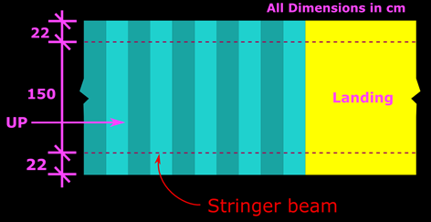
The following fig. 16.84 shows the part view of a stair
Fig.16.84
Part view of a stair
Part view of a stair cantilevering from both sides of a stringer beam. 
The waist slab is cantilevering on both sides of the stringer beam. The load calculation procedure is same as that of the other types of transverse stairs that we saw before. So we can use the same Eq.16.25 for the calculation of the loads. From this eq., we will get w1 , the load per 1m length, on a 1m wide strip. If the cantilevering length on both the sides are equal, we need to do the design of only one side as shown in the line diagram below:
Fig.16.85
Line diagram for stairs cantilevering on both sides of a stringer beam
The effective span l of the cantilever (cl.22.2.c) is the length of the cantilever up to the face of the support plus half the effective depth. For initial proportioning, we can assume the thickness of waist slab to be clear length of cantilever/5 . However, this should be finalized only after the complete design and various checks.

In the next section, we will see a solved example of the above type of stairs.

PREVIOUS     CONTENTS       NEXT                                        

                            Copyright©2016 limitstatelessons.blogspot.com - All Rights Reserved

Thursday, March 5, 2015

Chapter 16 (cont..12)

The following solved example illustrates the design of a transverse stair.
The reinforcement details according to the above solved example is shown in the figs.16.64 and 16.65 given below:
Fig.16.64
Sectional elevation of transverse stair
Sectional elevation showing the reinforcement details of a transverse staircase supported on two stringer beams
Fig.16.65
Section XX
Section showing the reinforcement details of a transverse staircase supported on two stringer beams.
We will now discuss the various features of the above two figs:
The main bars are given as the bottom most layer. The distributor bars are given as the second layer from the bottom. This arrangement will give maximum possible effective depth ‘d’ for the section. From the section XX, we can see that the main bars are given two 90o bends at both the ends. This will give a 'hook' like arrangement at both ends. The top portion of these 'hooks' will act as the steel required for resisting any possible hogging moment at the supports. The length required for this top steel is 0.15l, where l is the effective span of the waist slab. But the area required for this top steel is only half of that at the mid span. So, as shown in the inset, only alternate bars are given these hooks.
The distributor bars are of mild steel. So the symbol Φ is given to denote them.
In the above example, only a part plan (shown in the fig.16.65 below) of the stair was given along with the problem data.
Fig.16.65
Problem data of solved example 16.3
This is because, this small portion is sufficient for defining the problem of this type of a transverse stair. Some times this stair may have a landing also as shown below.
Fig.16.66
Landing in a transverse stair
In this case also the sloping portion can be analysed and designed by the same procedure, and the landing can be analysed and designed as a simply supported one-way slab.

Stairs cantilevering from the side of a beam:

The following fig.16.67 shows the part view of a stair.
Fig.16.67
View of a cantilever stair
It is projecting from the side of a wall. The wall is shown in a finished state. So we cannot see more details. The fig. below shows the view before the plastering is applied to the wall.
Fig.16.68
View of a stair cantilevering from a stringer beam
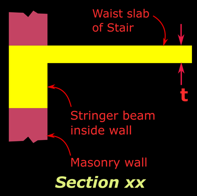
We can see that the stair is projecting from the side of a beam, which is concealed inside the wall. In actual construction, the beam (which frames into columns) and the waist slab will be cast first, and after curing and removal of form works, the masonry wall will be constructed above and below the beam. The elevation and section are shown in the figs. below:
Fig.16.69
Part elevation view of cantilever stairs
Fig.16.70
Section XX
Section XX
The waist slab bends in a direction perpendicular to the direction of travel of the pedestrians, and so it is a transverse stair. The load calculation procedure is the same as that for the transverse stair supported on two stringer beams. So we can use the same Eq.16.25. The line diagram for the analysis will be as shown below:
Fig.16.80
Line diagram for cantilever stairs

The effective span l of the cantilever (cl.22.2.c) is the length of the cantilever up to the face of the support plus half the effective depth. For initial proportioning, we can assume the thickness of waist slab to be clear length of cantilever/10 . However, this should be finalized only after the complete design and doing the various checks.
In the next section, we will see a solved example of the above type of stairs.

PREVIOUS      CONTENTS      NEXT

             Copyright ©2015 limitstatelessons.blogspot.com - All Rights Reserved