In the previous section we discussed the special precautions to be taken in the arrangement of reinforcements at Landings. In this section we continue the discussion on stairs in general. We will now discuss about a different type of stair.
Right angled stairs
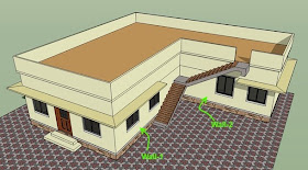
The stair shown in fig.16.30 below has two flights. The second flight is deviating from the first flight at an angle of 90o.
Fig.16.30
Stair taking a right angled turn
The first flight AB is supported on the ground at A, and on the wall-2 at B. The second flight CD is supported on wall-1 at C and on a beam at D. [At the time of construction, the walls 1 and 2 are stopped at the level of the bottom surface of the intermediate landing, so that the landing can be extended into the walls. After the casting and curing of landing and flight AB, the wall construction is resumed. The bars for CD are extended from the landing because CD can be casted only after completing wall-2, as it rests on the beam at D. The safety and stability of the beam at D should be carefully checked.] The bearing of the landing on the two walls can be seen in the plan view given below:
Fig.16.31
Plan view of right angled stair
For analysis, we have to draw the line diagram of each of the flights separately. The line diagrams are drawn from support to support. That is., from A to B, and from C to D. This is shown in figs.16.32 and 16.33 below.
We have to make a modification to the loads on the intermediate landing. It can be explained as follows: • We are designing the flights separately.
• When we assign loads to each flights separately, the loads coming on the intermediate landing will be assigned to both the flights.
• If we assign the full landing load w2 to one flight, it will mean that, the full load w2 acting on the landing is resisted by that flight only. It will also mean that the other flight does not have to resist w2
• But we know that both flights will take part in resisting w2. In other words, w2 contributes towards the bending of both the flights.
• So if we assign the full w2 to any one stair, there will be under estimation of the load on the other stair
• On the other hand, if we assign full w2 to both the flights, there will be over estimation. This is because, neither of the flights have to resist the full w2.
• So we give a part of w2 for one flight, and the remaining part for the other flight. In usual design practice, this 'part' is exact 50%. That is., 0.5w2 is given to one flight and 0.5w2 is given to the other flight.
• Thus, we first calculate w2 on the landing as usual, and then assign 0.5w2 for the landing common to each flight. This is shown in the line diagrams below.
Fig.16.32Line diagram for flight AB
Fig.16.33
Line diagram for flight CD
It may be noted that the modification factor of 0.5 is not applied to w2 on the topmost landing. This is because, it is not a common landing, and so, duplication does not occur. Also note that, the last step of flight AB should be of reinforced concrete as shown in fig.16.32. This is to ensure the smooth continuation of the main bars of flight CD into wall-1.
Once the line diagrams are prepared, we can do the analysis to determine the maximum bending moments, and then do the design as usual.
Stairs supported on landings
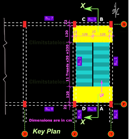
In the cases that we saw so far, the flights were supported on walls or beams. Now we will consider a type of longitudinal stair in which the the flights are supported by 'landing slabs'. To fully understand such a support, we have to get more details of the building. So let us start from the 'Key plan'. Fig.16.34 below shows a part of the key plan of a two storey building. The plan of the stairs in Floor 2 is shown within the key plan.
Fig.16.34
Portion of the key plan showing the Staircase portion
The sectional view is shown in the fig.16.35 below:
Fig.16.35
Sectional elevation
The beams and columns in the above figs. are named according to the specifications given in SP34. For example, COL 2 Q1 indicates the column Q1 (the column at the North East corner of the building) in Floor 2.
We can think about the supports of the stair in this way:
Flight AB can be supported at A on Bm 4 (of Floor1). At B, it can be supported on a brick wall built above Bm 3 (parallel to the Risers). Flight CD can be supported at C on this brick wall. At D, it can be supported on Bm 4 (of Floor 2) So the flights will be spanning between these beams and the brick wall on Bm 3. That is.,
• Flight AB spans between Bm4 and wall above Bm3 [Both Bm4 and Bm3 are at level 1]
• Flight CD spans between wall above Bm3 and Bm4 [Bm3 is at level 1 and Bm4 is at level 2]
But such a brick wall above Bm3 is not shown in the sectional view. Also, at A and D, the the flights are not shown to have any bearing into the beams Bm4 on either levels. So how are the flights being supported? For the answer, we will look at the views given in the next section.


No comments:
Post a Comment